IS-IS Adjacency Formation and States
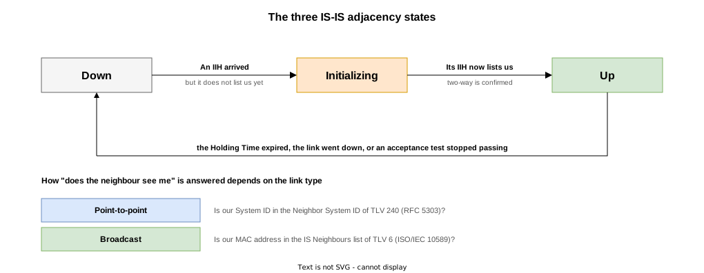
An IS-IS adjacency has only three states: Down, Initializing and Up. Because it is so simple, the real question is what conditions let an adjacency form.
This article covers the state transitions and the acceptance tests ISO/IEC 10589:2002 requires, checked against logs and captures. The IIH format is covered in IS-IS Packet Types and Header Format.
The Three States
| State | Meaning |
|---|---|
| Down | No adjacency. Either no IIH has arrived from the neighbour, or one arrived and could not be accepted |
| Initializing | An IIH has arrived, but whether the neighbour can see us is not yet known |
| Up | Two-way communication is confirmed, and LSP exchange begins |
ISO/IEC 10589:2002 describes adjacency formation in these three (the management enumeration also has failed).
Initializing exists because “an IIH arrived” and “the neighbour is receiving our IIHs” are different facts. The adjacency does not go Up until the second is established.
Initializing is not a stage every adjacency passes through. If the neighbour already recognises us, the adjacency goes straight from Down to Up — the case when only one router is restarted.
How “can the neighbour see me?” gets answered
The answer comes from different places depending on the link type.
| Link type | How it is confirmed | Source |
|---|---|---|
| Broadcast | Is our MAC address in TLV 6 (IS Neighbours) of the neighbour’s IIH? | ISO/IEC 10589:2002 8.4.2.5.1 |
| Point-to-point | Is our System ID in the Neighbor System ID of TLV 240 in the neighbour’s IIH? | RFC 5303 |
The broadcast case already had a two-way check in the standard. Clause 8.4.2.5.1 creates the adjacency in “initialising” and sets it Up when the neighbour reports our SNPA in its IIHs; if it disappears, the state returns to initialising (8.4.2.5.3).
Only point-to-point lacked such a mechanism. That is the subject of the next section.
Two-Way and Three-Way
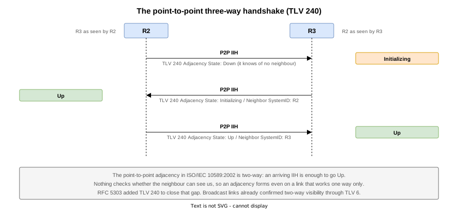
The point-to-point adjacency of ISO/IEC 10589:2002 is two-way: an IIH that passes the acceptance tests brings it Up, so an adjacency forms even on a link that works in only one direction.
RFC 5303 fixed this with the Point-to-Point Adjacency State TLV (240), carrying our view of the neighbour’s state and its System ID.
| Field | Content |
|---|---|
| Adjacency State | The adjacency state as we see it (0 = Up, 1 = Initializing, 2 = Down) |
| Extended Local Circuit ID | Our own circuit identifier, widened to four bytes |
| Neighbor System ID | The neighbour’s System ID. Its presence is the proof that we can see them |
| Neighbor Extended Local Circuit ID | The neighbour’s circuit identifier |
A router receiving an IIH without its own System ID stays in Initializing.
This TLV does not exist in ISO/IEC 10589 (the standard defines only CODEs 1 to 10 and 14).
What Has to Match
An IIH passes a series of tests before Up, in this order.
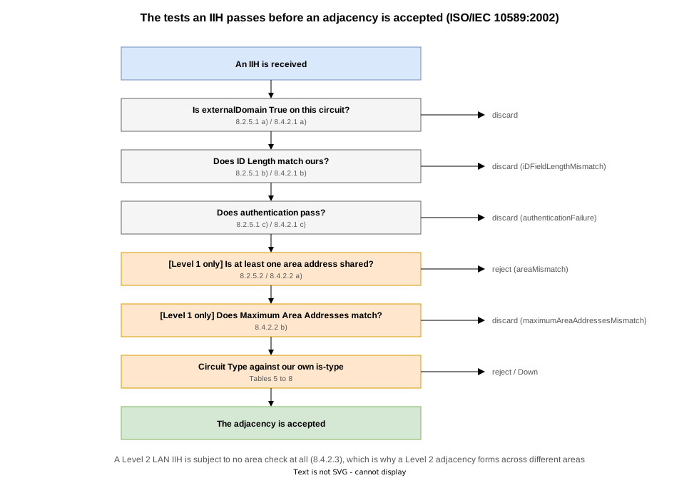
The tests common to every IIH
Point-to-point (8.2.5.1) and broadcast (8.4.2.1) specify exactly the same three.
| Test | What happens if it fails |
|---|---|
The receiving circuit’s externalDomain attribute must not be True | The PDU is discarded |
ID Length must match the value used in our routeing domain | The PDU is discarded and an iDFieldLengthMismatch event is generated |
| Authentication (password) must pass | The PDU is discarded and an authenticationFailure event is generated |
Authentication is covered in IS-IS Authentication (hello-password and lsp-password).
Level 1 and Level 2 are asymmetric
Past the common tests, what gets checked changes sharply with the level.
| Level | Area address check |
|---|---|
| Level 1 | At least one area address must match, or the adjacency is rejected and an areaMismatch event generated (8.4.2.2 a). Maximum Area Addresses is checked too (8.4.2.2 b) |
| Level 2 | No area check at all. The standard simply says that on receiving a Level 2 LAN IIH the IS accepts the adjacency and sets neighbourSystemType to “L2 Intermediate System” (8.4.2.3) |
This asymmetry is why a mismatched area blocks a Level 1 adjacency but not a Level 2 one (IS-IS Level 1 and Level 2).
An IS that implements only 3 for Maximum Area Addresses may omit that check (8.4.2.2 b); Cisco fixes it at 3, so the check is inert.
Circuit Type against is-type
Finally the Circuit Type of the IIH is judged against our own is-type. For point-to-point, ISO/IEC 10589:2002 gives this as state Tables 5 to 8; Table 5 covers Level 1 where the areas match.
Circuit Type in the received IIH | No adjacency yet | A Level 1 adjacency already exists |
|---|---|---|
| Level 1 only | Up (as Level 1) | Kept |
| Level 2 only | Rejected (wrongSystemType) | Taken Down and deleted |
| Level 1 and 2 | Up (as Level 1) | Kept |
Circuit Type is the low two bits of a byte in the IIH’s fixed part, and the is-type setting lands directly in it. The pair of is-type values at the two ends decides the level.
MTU is not a test; it works as a side effect
MTU appears nowhere in those tests. IS-IS has no MTU field; it detects a mismatch indirectly through IIH padding.
An IIH is padded with TLV 8 to at least maxsize − 1 bytes (8.2.4 / 8.4.2). The end with the smaller MTU cannot receive it, so no IIH arrives and no adjacency forms.
maxsize is the larger of the link’s block size and the maximum LSP size. Lowering only the link MTU leaves the target at the LSP size (1492 by default), so even the end with the reduced MTU keeps sending IIHs larger than its own MTU.
When only one side has the smaller MTU, the two ends see different things.
| Side | What it sees |
|---|---|
| The smaller MTU | Cannot receive the neighbour’s large IIHs, so no adjacency appears at all |
| The larger MTU | Does receive the neighbour’s smaller IIHs and knows it exists, but those IIHs never carry its System ID, so it stalls in Initializing |
Padding is covered in IS-IS Packet Types and Header Format; STEPs 2 and 3 confirm the behaviour.
Verification on Real Equipment
The test environment

The topology contains both a broadcast link and a point-to-point link.
| Router | NET | is-type | Connections |
|---|---|---|---|
| R1 | 49.0001.0010.0100.1001.00 | level-1 | LAN only |
| R2 | 49.0001.0020.0200.2002.00 | (default = level-1-2) | LAN plus the P2P link to R3 |
| R3 | 49.0002.0030.0300.3003.00 | (default = level-1-2) | P2P to R2 only |
R1 and R2 share a broadcast segment (10.1.0.0/24) in area 49.0001; R2 and R3 are joined by a point-to-point link (10.2.3.0/24). R3 is in area 49.0002, so R2–R3 is Level 2.
IS-IS 1 Level-1 adjacencies:
System Id      Interface                SNPA           State Hold Changed  NSF IPv4 IPv6
                                                                               BFD  BFD
R1             Gi0/0/0/0                5254.0054.6449 Up    21   00:04:16 Yes None None
  Area Address:           49.0001
  Neighbor IPv4 Address:  10.1.0.1*
  DIS Priority:           64
  Local Priority:         64 (DIS)
  Neighbor Priority:      64
  Topology:               IPv4 Unicast
  BFD Status:             Neighbor Useable (BFD Not Configured)

Total adjacency count: 1

IS-IS 1 Level-2 adjacencies:
System Id      Interface                SNPA           State Hold Changed  NSF IPv4 IPv6
                                                                               BFD  BFD
R3             Gi0/0/0/1                *PtoP*         Up    27   00:04:12 Yes None None
  Area Address:           49.0002
  Neighbor IPv4 Address:  10.2.3.3*
  Topology:               IPv4 Unicast
  BFD Status:             Neighbor Useable (BFD Not Configured)
  Adjacency Flaps:        0

Total adjacency count: 1
From R2, R1 is Level 1 and R3 is Level 2. R3 is in a different area and the adjacency still forms, because Level 2 performs no area check.
Two IOS XR commands proved decisive for this verification.
| Command | What it shows |
|---|---|
show isis adjacency-log | The state transitions themselves. Lists, per level, when and on which interface an adjacency went d -> i, i -> u and so on |
show isis trace all | include 3WAY | The three-way handshake being evaluated, down to whether a received IIH carried our own System ID |
show isis trace selects by severity (all / detailed / only / severe / standard). all runs to nearly 4000 lines, so narrow it on the device with | include.
The test STEPs
| STEP | Action | Purpose |
|---|---|---|
| 0 | Initial state | Steady-state adjacencies and the Changed column |
| 1 | process restart isis on R2 and R3 | Follow Down to Initializing to Up in the log and the capture |
| 2 | Change the interface MTU on R3’s side only | Confirm the adjacency does not form; padding doing its job |
| 3 | Leave the MTU mismatched and apply hello-padding disable to both ends | Confirm the adjacency comes up despite the mismatch |
| 4 | Restore the MTU and padding (final state) | Same as the initial state |
Following the Transitions (STEP 1)
process restart isis was run on R2 and R3, and the adjacencies rebuilt.
The transitions are in the log verbatim
  IS-IS 1  Level 1  Adjacency Log                Capacity: 100, Size: 1

When          System          Interface          State   Details
--- Wed Sep  9 2026 ---
03:52:04.514  R1              Gi0/0/0/0          d -> u  New adjacency
                                                         IPv4 Unicast Up

  IS-IS 1  Level 2  Adjacency Log                Capacity: 100, Size: 2

When          System          Interface          State   Details
--- Wed Sep  9 2026 ---
03:52:04.902  R3              Gi0/0/0/1          d -> i
03:52:05.510  R3              Gi0/0/0/1          i -> u  New adjacency
IPv4 Unicast Upd, i and u are Down, Initializing and Up. With R3, d -> i is followed about 0.6 seconds later by i -> u.
With R1 it reads d -> u, skipping Initializing. R1 kept running throughout, so the first IIH R2 received after coming back (with R2’s MAC in TLV 6) already proved two-way visibility.
The log from the lab’s initial boot, when all three came up together, shows both going through two stages.
  IS-IS 1  Level 1  Adjacency Log                Capacity: 100, Size: 2

When          System          Interface          State   Details
--- Wed Sep  9 2026 ---
03:46:26.689  R1              Gi0/0/0/0          d -> i
03:46:29.679  R1              Gi0/0/0/0          i -> u  New adjacency
                                                         IPv4 Unicast Up
Initializing appearing only when the neighbour does not know us yet is the difference between the two logs.
The three-way handshake in the capture
The R2–R3 capture shows TLV 240’s Adjacency State changing across four consecutive IIHs.
ISIS HELLO
    .... ..11 = Circuit type: Level 1 and 2 (0x3)
    0000 00.. = Reserved: 0x00
    SystemID {Sender of PDU}: 0020.0200.2002
    Holding timer: 30
    PDU length: 1497
    Local circuit ID: 0
    Point-to-point Adjacency State (t=240, l=5)
        Type: 240
        Length: 5
        Adjacency State: Down (2)
Extended Local circuit ID: 0x00000005The IIH R2 sent right after restarting. Length: 5, with no Neighbor SystemID. RFC 5303 permits the shorter TLV in this state.
ISIS HELLO
    .... ..11 = Circuit type: Level 1 and 2 (0x3)
    0000 00.. = Reserved: 0x00
    SystemID {Sender of PDU}: 0030.0300.3003
    Holding timer: 30
    PDU length: 1497
    Local circuit ID: 0
    Point-to-point Adjacency State (t=240, l=15)
        Type: 240
        Length: 15
        Adjacency State: Initializing (1)
        Extended Local circuit ID: 0x00000002
        Neighbor SystemID: 0020.0200.2002
Neighbor Extended Local circuit ID: 0x00000005R3’s reply. The Length is now 15 and Neighbor SystemID: 0020.0200.2002 (R2) is present — “I can see you”.
R2 finds its own System ID and goes Up; in No.11 it returns Neighbor SystemID: 0030.0300.3003, and R3 goes Up too.
ISIS HELLO
    .... ..11 = Circuit type: Level 1 and 2 (0x3)
    0000 00.. = Reserved: 0x00
    SystemID {Sender of PDU}: 0030.0300.3003
    Holding timer: 30
    PDU length: 1497
    Local circuit ID: 0
    Point-to-point Adjacency State (t=240, l=15)
        Type: 240
        Length: 15
        Adjacency State: Up (0)
        Extended Local circuit ID: 0x00000002
        Neighbor SystemID: 0020.0200.2002
Neighbor Extended Local circuit ID: 0x00000005Put together: reaching Up takes three exchanges.
| No. | Sender | Adjacency State | Neighbor SystemID |
|---|---|---|---|
| 9 | R2 | Down (2) | absent (Length: 5) |
| 10 | R3 | Initializing (1) | 0020.0200.2002 (R2) |
| 11 | R2 | Initializing (1) | 0030.0300.3003 (R3) |
| 12 | R3 | Up (0) | 0020.0200.2002 (R2) |
The three-way decision in the trace
show isis trace records the same decision.
Sep  9 03:46:23.771 isis/1/hlo ... isis_osi_send_p2p_hello:1168      ADJ_SEND_P2P_DO_IETF_3WAY Gi0/0/0/1 L1L2
Sep  9 03:46:33.001 isis/1/hlo ... isis_osi_adj_p2p_3way_validate:5244  ADJ_RECV_P2P_3WAY_IETF_ACCEPT_MISSING L1L2 Gi0/0/0/1 5254.005f.3ecc P2P IIH
Sep  9 03:46:33.302 isis/1/hlo ... isis_osi_send_p2p_hello:1168      ADJ_SEND_P2P_DO_IETF_3WAY Gi0/0/0/1 L1L2
Sep  9 03:46:33.612 isis/1/hlo ... isis_osi_adj_p2p_3way_validate:5179  ADJ_RECV_P2P_3WAY_NBR_ADJ_STATE_CHANGE L1L2 Gi0/0/0/1 5254.005f.3ecc P2P IIH
Sep 9 03:46:33.612 isis/1/hlo ... isis_osi_adj_p2p_3way_validate:5337 ADJ_RECV_P2P_3WAY_IETF_ACCEPT_MATCH L1L2 Gi0/0/0/1 5254.005f.3ecc P2P IIH| Keyword | Meaning |
|---|---|
ADJ_SEND_P2P_DO_IETF_3WAY | The outgoing P2P IIH carried the RFC 5303 three-way information |
ADJ_RECV_P2P_3WAY_IETF_ACCEPT_MISSING | The received IIH did not contain our System ID |
ADJ_RECV_P2P_3WAY_IETF_ACCEPT_MATCH | The Neighbor System ID in the received IIH matched ours |
MISSING followed by MATCH maps onto No.9 and No.10. The word IETF is there because this is RFC 5303 behaviour.
Making the MTUs Disagree (STEP 2)
The interface MTU was lowered on R3’s side only.
interface GigabitEthernet0/0/0/0
 mtu 1400
The IOS XR interface MTU defaults to 1514; minus the 14-byte Ethernet and 3-byte LLC headers, IS-IS sees 1497, or 1383 after setting 1400.
The two ends see it asymmetrically
RP/0/RP0/CPU0:R3#show isis neighbors
Wed Sep  9 04:01:07.839 UTC

IS-IS 1 neighbors:
System Id Interface SNPA State Holdtime Type IETF-NSFRP/0/RP0/CPU0:R2#show isis neighbors
Wed Sep 9 04:00:52.063 UTC
IS-IS 1 neighbors:
System Id Interface SNPA State Holdtime Type IETF-NSF
R1 Gi0/0/0/0 5254.0054.6449 Up 28 L1 Capable
R3 Gi0/0/0/1 *PtoP* Init 25 L2 Capable
Total neighbor count: 2R3, whose MTU was lowered, has no adjacency; R2 is stuck in Init.
R2’s 1497-octet IIHs do not fit R3’s MTU of 1383 and never arrive. R3’s IIHs do reach R2, but carry no Neighbor SystemID, so R2 remains in Initializing.
R3 spells out the reason.
  Media Type:               P2P
  Circuit Number:           0
  Last IIH Received:        03:56:37 (00:04:29 ago), 1497 octets
  Last PDU Rejected:        04:01:02 (5.57 sec ago), 1497 octets, P2P IIH, PDU larger than our MTU

  CLNS I/O
    Protocol State:         Up
    MTU:                    1383 (MTU is too small: lsp-mtu is 1492)
PDU larger than our MTU: the IIH is dropped for being too big. Last IIH Received is frozen at a time before the MTU change.
The three-way handshake is what drops the adjacency
R2’s log recorded the event.
03:52:04.902  R3              Gi0/0/0/1          d -> i
03:52:05.510  R3              Gi0/0/0/1          i -> u  New adjacency
                                                         IPv4 Unicast Up
03:57:08.033  R3              Gi0/0/0/1          u -> i  3-way state down
                                                         IPv4 Unicast Down
The reason reads 3-way state down. R2 is still receiving R3’s IIHs; it dropped the adjacency because its own System ID vanished from them.
Under the two-way behaviour of ISO/IEC 10589:2002, R2 would keep the adjacency Up purely because IIHs were arriving — a one-way adjacency.
That is the hole RFC 5303 closed, and its work shows up as a single log line.
R3’s log records the same event for a different reason.
03:52:04.805  R2              Gi0/0/0/0          d -> i
03:52:05.206  R2              Gi0/0/0/0          i -> u   New adjacency
03:57:07.824  R2              Gi0/0/0/0          u -> d   Holdtime expired
                                                          IPv4 Unicast Down
Receiving no IIHs, R3 loses it to Holding Time expiry. One MTU mismatch surfaces as 3-way state down at one end and Holdtime expired at the other.
The padded IIHs travel only one way
The capture shows the situation settling into a steady state.
$ tshark -r isis-adj-mtu.pcap -n -Y "isis.type == 17" \
    -T fields -e eth.src -e frame.len -e isis.hello.adjacency_state | sort | uniq -c
   2 52:54:00:5f:3e:cc	1509	0
  18 52:54:00:5f:3e:cc	1509	2
   2 52:54:00:5f:3e:cc	1514	0
   4 52:54:00:93:4c:03	1514	0
  18 52:54:00:93:4c:03	1514	1
-Y "isis.type == 17" keeps the point-to-point IIHs and sort | uniq -c counts each combination of the three fields:
| Column | Comes from | Content |
|---|---|---|
| 1st | uniq -c | Number of packets with this combination |
| 2nd | -e eth.src | Source MAC address. 52:54:00:93:4c:03 is R2, 52:54:00:5f:3e:cc is R3 |
| 3rd | -e frame.len | Frame length in bytes |
| 4th | -e isis.hello.adjacency_state | The Adjacency State of TLV 240. 0 = Up, 1 = Initializing, 2 = Down |
Re-read in time order, the five rows lay out what happened around the MTU change.
| Count | Sender | Frame length | State | When |
|---|---|---|---|---|
| 2 | R3 | 1514 | Up (0) | Before the MTU change. Both ends at 1514 bytes, adjacency Up |
| 4 | R2 | 1514 | Up (0) | The same (R2 stays at 1514 for the whole capture) |
| 2 | R3 | 1509 | Up (0) | Just after the MTU change. Only R3’s frames shrank to 1509; the adjacency is still Up |
| 18 | R2 | 1514 | Initializing (1) | The steady state once the mismatch took hold. R3 is visible, but it does not recognise R2 |
| 18 | R3 | 1509 | Down (2) | The same steady state. Not one IIH from R2 arrives, so R3 sees nobody |
The first three rows are the first dozen seconds; the remaining 36 packets are all in the state of the bottom two rows.
The third row (R3 at 1509 but still Up) is the few seconds between the frames shrinking and the adjacency dropping.
Download the pcap of R2's packet from the counts above (No.10, Adjacency State: Initializing)R3’s IIHs being 1509 bytes, larger than its own MTU, follows from maxsize staying at the LSP size of 1492 (MTU is not a test; it works as a side effect).
XR’s warning MTU: 1383 (MTU is too small: lsp-mtu is 1492) says the same thing.
Turning Padding Off (STEP 3)
With the MTUs still mismatched, padding was disabled on the IS-IS interfaces at both ends.
router isis 1
 interface GigabitEthernet0/0/0/1      (GigabitEthernet0/0/0/0 on R3)
hello-padding disableRP/0/RP0/CPU0:R3#show isis neighbors
Wed Sep 9 04:05:36.746 UTC
IS-IS 1 neighbors:
System Id Interface SNPA State Holdtime Type IETF-NSF
R2 Gi0/0/0/0 *PtoP* Up 22 L2 Capable
Total neighbor count: 1The adjacency comes up, because the IIHs now fit R3’s MTU.
03:57:07.824  R2              Gi0/0/0/0          u -> d   Holdtime expired
                                                          IPv4 Unicast Down
04:01:44.110  R2              Gi0/0/0/0          d -> i
04:01:44.718  R2              Gi0/0/0/0          i -> u   New adjacency
                                                          IPv4 Unicast Up
The routes arrived too.
RP/0/RP0/CPU0:R3#show route isis
Wed Sep  9 04:05:35.890 UTC

i L2 1.1.1.1/32 [115/20] via 10.2.3.2, 00:03:51, GigabitEthernet0/0/0/0
i L2 2.2.2.2/32 [115/10] via 10.2.3.2, 00:03:51, GigabitEthernet0/0/0/0
i L2 10.1.0.0/24 [115/20] via 10.2.3.2, 00:03:51, GigabitEthernet0/0/0/0
The adjacency is Up but the MTUs still differ
The MTUs are still mismatched, yet the adjacency forms and nothing in show looks wrong. A configuration IS-IS was designed to reject now goes through.
No damage appears only because the LSPs are small. The moment an LSP lands between 1384 and 1492 octets, that LSP alone stops arriving, and the databases diverge while the adjacency stays Up.
The router keeps warning about it even in this state.
  CLNS I/O
    MTU:                    1383 (MTU is too small: lsp-mtu is 1492)
An adjacency being Up and a link being healthy are two different things. Before using hello-padding disable, confirm by other means that the MTUs agree.
STEP 4 restored the MTU and hello-padding, returning everything to the initial state.
Verification Config and show Output
At every STEP the following three files were collected per router. The verification config is the ..._run.txt file (final state: STEP 4).
| File | Content |
|---|---|
..._show.txt | show version / show interface description / show route / show route isis / show isis / show isis hostname / show isis interface / show isis interface brief / show isis neighbors / show isis neighbors detail / show isis database / show isis database detail / show isis topology / show isis adjacency / show isis adjacency detail / show isis adjacency-log / show isis trace standard | include ADJ / show isis trace all | include 3WAY / show isis spf-log / show isis lsp-log / show isis statistics / show cef |
..._log.txt | show logging narrowed to that STEP (STEP 0 holds the full history since boot) |
..._run.txt | show running-config at that STEP (that is, the verification config for the STEP) |
The final configuration applies point-to-point only between R2 and R3, with mtu 1400 and hello-padding disable removed.
STEP 0: initial state
| Router | show output | syslog | running-config |
|---|---|---|---|
| R1 | show | log | run |
| R2 | show | log | run |
| R3 | show | log | run |
STEP 1: process restart isis on R2 and R3
| Router | show output | syslog | running-config |
|---|---|---|---|
| R1 | show | log | run |
| R2 | show | log | run |
| R3 | show | log | run |
STEP 2: interface MTU on R3 changed to 1400
| Router | show output | syslog | running-config |
|---|---|---|---|
| R1 | show | log | run |
| R2 | show | log | run |
| R3 | show | log | run |
STEP 3: hello-padding disable applied with the MTU still mismatched
| Router | show output | syslog | running-config |
|---|---|---|---|
| R1 | show | log | run |
| R2 | show | log | run |
| R3 | show | log | run |
STEP 4: MTU and hello-padding restored (final state)
| Router | show output | syslog | running-config |
|---|---|---|---|
| R1 | show | log | run |
| R2 | show | log | run |
| R3 | show | log | run |
There are four capture files.
Download the R2-R3 link capture, STEP 1 (isis-adj-p2p.pcap)
Download the LAN segment capture, STEP 1 (isis-adj-lan.pcap)
Download the capture taken during the MTU mismatch, STEP 2 (isis-adj-mtu.pcap)
Download the capture taken with padding disabled, STEP 3 (isis-adj-padoff.pcap)
References
| Standard | Title | Summary |
|---|---|---|
| ISO/IEC 10589:2002 (Second Edition) | Intermediate System to Intermediate System intra-domain routeing information exchange protocol | The IS-IS specification itself. This article draws on 8.2.4 to 8.2.6 (the point-to-point adjacency procedures), 8.4.2 (the broadcast procedures, in particular the acceptance tests in 8.4.2.1, Level 1 in 8.4.2.2, Level 2 in 8.4.2.3 and new adjacencies in 8.4.2.5), Tables 5 to 8 (the combinations with Circuit Type) and 8.2.4 / 8.4.2 (IIH padding). |
| RFC 1142 | OSI IS-IS Intra-domain Routing Protocol | A republication of the ISO 10589 Draft Proposal (1990), now Historic. It must not be referenced in place of ISO/IEC 10589 (see RFC 7142). |
| RFC 7142 | Reclassification of RFC 1142 to Historic | States that references should be to ISO/IEC 10589:2002, Second Edition. |
| RFC 5303 | Three-Way Handshake for IS-IS Point-to-Point Adjacencies | Defines TLV 240, and describes the problem with the two-way point-to-point adjacency of ISO/IEC 10589 together with its remedy. |
| RFC 1195 | Use of OSI IS-IS for Routing in TCP/IP and Dual Environments | The extension that carries IP routes. |
Related Articles
- What is IS-IS
- IS-IS NSAP Addresses and the NET (System ID)
- IS-IS Multiple Area Addresses (Multihoming), Merging and Splitting Areas
- IS-IS Level 1 and Level 2 (the hierarchy)
- IS-IS Packet Types and Header Format
- IS-IS Adjacency Formation and States
- IS-IS DIS and the Pseudonode
- IS-IS Network Types (broadcast / point-to-point)
- IS-IS Metrics (narrow and wide)
- IS-IS Authentication (hello-password and lsp-password)
- IS-IS LSPs and the Link-State Database
- The Main IS-IS TLVs
- IS-IS Flooding and LSDB Synchronisation
- IS-IS SPF Computation and Route Selection
- IS-IS ECMP (Equal-Cost Multipath)
- The IS-IS ATT Bit and the Level 1 Default Route
- IS-IS Route Leaking and the Up/Down Bit
- IS-IS Route Summarization
- The IS-IS Overload Bit
- IS-IS IPv6 Support and Multi-Topology (TLV 236 / MT ID 2)
- IS-IS Hello and Holding Time
- IS-IS Convergence Timers (SPF / LSP Generation)
- IS-IS Flooding Timers (LSP Interval, Retransmission, CSNP / PSNP)
- IS-IS Link Failure and Path Switchover
- IS-IS Redistribution (connected / static)
- IS-IS Redistribution of BGP Routes