IS-IS DIS and the Pseudonode
On a broadcast segment IS-IS elects one router as the representative, the DIS (Designated Intermediate System). It corresponds to OSPF’s DR, but the resemblance stops at the idea of electing a representative.
The DIS’s central job is to build a fictitious node in the database, the pseudonode, on everyone’s behalf. This article checks what the pseudonode solves, how the DIS is elected, and how it differs from OSPF’s DR.
The Priority and LAN ID fields of a LAN IIH are covered in IS-IS Packet Types and Header Format.
What the Pseudonode Solves

Represented literally, a broadcast segment is n routers in a full mesh, n(n−1)/2 links: 45 for ten routers, and growing fast.
Clause 3.6.7 of ISO/IEC 10589:2002 treats the segment itself as a single node.
Where a broadcast subnetwork has n connected Intermediate systems, the broadcast subnetwork itself is considered to be a pseudonode. The pseudonode has links to each of the n Intermediate and End systems. Each of the ISs has a single link to the pseudonode (rather than n-1 links to each of the other Intermediate systems).
The link count drops to n. Clause 7.2.3 states that each router reports only its link to the pseudonode, and the DIS constructs the pseudonode’s LSPs on its behalf.
That is what the DIS fundamentally does: ghost-write the LSP of a fictitious node called the LAN.
The Pseudonode LSP Carries a Metric of Zero

Traversing a pseudonode means two links, R2 to the pseudonode and the pseudonode to R3, which risks counting the cost twice.
The standard resolves this by making every metric in the pseudonode’s LSP zero; the footnote to 7.2.3 gives the reason.
They are set to zero metric values since they have already been assigned metrics by the link to the pseudonode. Assigning a non-zero metric in the pseudonode LSP would have the effect of doubling the actual value.
The cost is paid only in the router-to-pseudonode direction, so the segment counts correctly as a single hop.
Electing the DIS
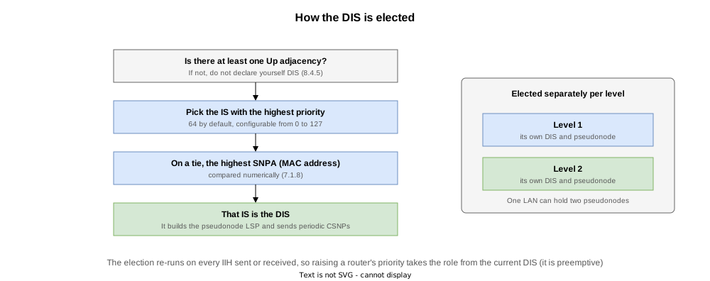
The rule is in clause 8.4.5 of ISO/IEC 10589:2002, and it is very short.
A LAN Designated Intermediate System is the highest priority Intermediate system in a particular set on the LAN, with numerically highest MAC source SNPAAddress breaking ties.
| Order | Condition |
|---|---|
| 1 | The IS with the highest priority. IOS XR defaults to 64, configurable from 0 to 127 |
| 2 | On a tie, the IS with the numerically highest SNPA (MAC address) |
The standard adds that a router must not declare itself DIS until it has at least one Up adjacency, so that a box with a broken receiver cannot decide it is the DIS.
Each level elects its DIS separately; if they differ, two pseudonodes exist.
Differences from OSPF’s DR
The designs differ in three points.
| Aspect | OSPF DR | IS-IS DIS |
|---|---|---|
| Backup | There is a BDR, ready to take over instantly | There is none. ISO/IEC 10589 has no concept of a backup DIS; when one goes, the election simply re-runs |
| Raising a priority | Does not take over (non-preemptive). The existing DR stays | Takes over (preemptive). Clause 7.2.3 says a router resigns because “some other Intermediate system of higher priority has taken over that function” |
| Adjacencies | Full adjacency only with the DR and BDR | Adjacency with everyone. What is collapsed is the database representation, not the adjacencies |
The pseudonode is purely a database representation; it does not reduce the number of adjacencies. Each router on a four-router LAN holds three adjacencies.
The election re-runs on every IIH sent or received (8.4.5), so nothing like a BDR is required.
Verification on Real Equipment
The test environment

Four routers on a single broadcast segment (10.1.0.0/24), all in area 49.0001, all level-1-2, with no point-to-point.
| Router | NET | SNPA (MAC address) |
|---|---|---|
| R1 | 49.0001.0010.0100.1001.00 | 5254.00a3.a6fa |
| R2 | 49.0001.0020.0200.2002.00 | 5254.0075.d9dc |
| R3 | 49.0001.0030.0300.3003.00 | 5254.003a.d413 |
| R4 | 49.0001.0040.0400.4004.00 | 5254.0089.cc01 |
Every priority is the default 64, so R1, with the highest SNPA, should become the DIS.
The test STEPs
| STEP | Action | Purpose |
|---|---|---|
| 0 | Initial state | The election result and the contents of the pseudonode LSP |
| 1 | Set R3’s priority to 100 | Preemption. Can R3, with the lowest MAC, take the role? |
| 2 | Set R2’s priority to 110 for Level 2 only | A per-level DIS. Do two pseudonodes appear on one LAN? |
| 3 | shutdown R3’s LAN interface | Re-election. Confirming there is no backup |
| 4 | Restore the priorities and the shutdown (final state) | Same as the initial state |
Two IOS XR commands proved useful.
| Command | What it shows |
|---|---|
show isis trace all | include ELECT | DIS_RUN_ELECTION / DIS_TRIGGER_ELECTION / DIS_ELECTION_RESULT_* — the election itself |
show isis trace all | include PSEUDO | LOCAL_PSEUDO_BUILD_START to LOCAL_PSEUDO_NARROW_LINK_ADD to LOCAL_PSEUDO_BUILD_END — the pseudonode LSP being assembled |
show isis trace selects by severity; all runs to nearly 4000 lines, so narrow it with | include (| include DIS matches the unrelated DIST_ entries).
The Initial DIS (STEP 0)
  Level-1
    Adjacency Count:        3
    Adjacency Flaps:        0
    LAN ID:                 R1.01
    Priority (Local/DIS):   64/64
    Next LAN IIH in:        1 s
    LSP Pacing Interval:    33 ms
    PSNP Entry Queue Size:  0
    Hello Interval:         10 s
    Hello Multiplier:       3
  Level-2
    Adjacency Count:        3
    Adjacency Flaps:        0
    LAN ID:                 R1.01
    Priority (Local/DIS):   64/64
LAN ID: R1.01 is the same at both levels, so R1 is the DIS for both. Priority (Local/DIS): 64/64 reads “our priority / the DIS’s priority”.
Adjacency Count: 3 shows that a pseudonode does not reduce the number of adjacencies.
Inside the pseudonode LSP
R1.01-00              0x00000008   0xb492        636  /*            0/0/0
  Metric: 0          IS R4.00
  Metric: 0          IS R3.00
  Metric: 0          IS R2.00
  Metric: 0          IS R1.00
R2.00-00              0x00000006   0x8090        619  /1200         0/0/0
  Area Address:   49.0001
  LSP MTU:        1492
  NLPID:          0xcc
  IP Address:     2.2.2.2
  Hostname:       R2
  Metric: 0          IP 2.2.2.2/32
  Metric: 10         IP 10.1.0.0/24
  Metric: 10         IS R1.01
The first part is the pseudonode LSP R1.01-00, listing all four routers with every metric zero.
R2’s own LSP has a single IS reference, Metric: 10 IS R1.01: each router reports only its one link to the pseudonode, as 7.2.3 requires.
The cost from R2 to R3 is 10 plus 0, giving 10. Had the pseudonode LSP carried 10, it would be 20, twice the real cost.
Taking the Role by Priority (STEP 1)
R3’s priority is raised to 100. R3 has the lowest SNPA, so it shows whether priority alone can win.
router isis 1
 interface GigabitEthernet0/0/0/0
priority 100IS-IS 1 (Level-1) Link State Database
LSPID LSP Seq Num LSP Checksum LSP Holdtime/Rcvd ATT/P/OL
R1.00-00 * 0x00000007 0x24d2 1100 /* 0/0/0
R1.01-00 0x00000009 0x9aef 0 (1099)/* 0/0/0
R2.00-00 0x00000008 0xa228 1100 /1200 0/0/0
R3.00-00 0x00000007 0x257b 1099 /1200 0/0/0
R3.01-00 0x00000001 0x60a9 1099 /1200 0/0/0
R4.00-00 0x00000008 0xa3d0 1100 /1200 0/0/0The old DIS’s pseudonode LSP R1.01-00 shows a Holdtime of 0 (purged), and R3.01-00 appears with sequence number 0x00000001.
This is the behaviour clause 7.2.3 of ISO/IEC 10589:2002 prescribes.
When an Intermediate system resigns as Designated Intermediate System, it shall initiate a network wide purge of its pseudonode Link State PDU(s) by setting their Remaining Lifetime to zero.
This shows that priority overrides the lowest MAC and that a change of DIS rebuilds the pseudonode LSP.
The handover in the capture
  No type   LSP-ID                    life seq
  23 L1 LSP 0010.0100.1001.01-00         0 0x00000008
  24 L2 LSP 0010.0100.1001.01-00         0 0x00000008
  ...
  41 L1 LSP 0030.0300.3003.01-00      1200 0x00000001
  43 L2 LSP 0030.0300.3003.01-00      1199 0x00000001
The old DIS’s pseudonode 0010.0100.1001.01-00 is purged with life=0 and the new 0030.0300.3003.01-00 is born with seq=1.
The re-election in the trace
Sep  9 06:51:42.059 isis/1/det ... isis_dis_run_election:778      DIS_ELECTION_RESULT_DIS_EXISTS L1 Gi0/0/0/0
Sep  9 06:51:42.059 isis/1/det ... isis_dis_run_election:778      DIS_ELECTION_RESULT_DIS_EXISTS L2 Gi0/0/0/0
Sep  9 06:51:43.049 isis/1/det ... isis_dis_trigger_election:964  DIS_TRIGGER_ELECTION L1 Gi0/0/0/0 0030.0300.3003
Sep  9 06:51:43.049 isis/1/det ... isis_dis_trigger_election:964  DIS_TRIGGER_ELECTION L2 Gi0/0/0/0 0030.0300.3003
DIS_TRIGGER_ELECTION ending with 0030.0300.3003 (R3) records that receiving R3’s IIH made R1 re-run the election, two seconds after the commit on R3 (06:51:41).
On R3, the new DIS, the assembly of the pseudonode LSP was recorded.
Sep  9 06:51:42.103 isis/1/lsp ... LOCAL_PSEUDO_BUILD_START L1 Gi0/0/0/0 Node Num: 1
Sep  9 06:51:42.103 isis/1/std ... LOCAL_PSEUDO_NARROW_LINK_ADD L1 Gi0/0/0/0 Node Num: 1 0030.0300.3003.00
Sep  9 06:51:42.103 isis/1/std ... LOCAL_PSEUDO_NARROW_LINK_ADD L1 Gi0/0/0/0 Node Num: 1 0010.0100.1001.00
Sep  9 06:51:42.103 isis/1/std ... LOCAL_PSEUDO_NARROW_LINK_ADD L1 Gi0/0/0/0 Node Num: 1 0020.0200.2002.00
Sep  9 06:51:42.103 isis/1/std ... LOCAL_PSEUDO_NARROW_LINK_ADD L1 Gi0/0/0/0 Node Num: 1 0040.0400.4004.00
Sep  9 06:51:42.103 isis/1/lsp ... LOCAL_PSEUDO_BUILD_END L1 Gi0/0/0/0 Node Num: 1 1
NARROW_LINK_ADD appears four times, the four routers on the LAN: the pseudonode LSP being assembled as “links to everyone on the LAN”.
A Different DIS per Level (STEP 2)
IOS XR can set the priority per level. R2’s Level 2 priority alone was raised to 110.
router isis 1
 interface GigabitEthernet0/0/0/0
priority 110 level 2 Level-1
Adjacency Count: 3
Adjacency Flaps: 0
LAN ID: R3.01
Priority (Local/DIS): 64/100
Level-2
Adjacency Count: 3
Adjacency Flaps: 0
LAN ID: R2.01
Priority (Local/DIS): 64/110The Level 1 DIS is R3 (100) and the Level 2 DIS is R2 (110).
The database shows two pseudonodes on the same LAN.
IS-IS 1 (Level-1) Link State Database
LSPID                 LSP Seq Num  LSP Checksum  LSP Holdtime/Rcvd  ATT/P/OL
R1.00-00            * 0x00000007   0x24d2        839  /*            0/0/0
R1.01-00              0x00000009   0x9aef        0 (838)/*          0/0/0
R2.00-00              0x00000008   0xa228        839  /1200         0/0/0
R3.00-00              0x00000007   0x257b        838  /1200         0/0/0
R3.01-00              0x00000001   0x60a9        838  /1200         0/0/0
R4.00-00              0x00000008   0xa3d0        839  /1200         0/0/0

 Total Level-1 LSP count: 6     Local Level-1 LSP count: 1

IS-IS 1 (Level-2) Link State Database
LSPID                 LSP Seq Num  LSP Checksum  LSP Holdtime/Rcvd  ATT/P/OL
R1.00-00            * 0x0000000f   0xfa2b        1097 /*            0/0/0
R1.01-00              0x00000009   0x9aef        0 (838)/*          0/0/0
R2.00-00              0x0000000f   0x807e        1096 /1200         0/0/0
R2.01-00              0x00000001   0xd556        1096 /1200         0/0/0
R3.00-00              0x0000000d   0x0acf        1097 /1200         0/0/0
R4.00-00              0x0000000e   0x8d24        1097 /1200         0/0/0
Level 1 holds R3.01-00 and Level 2 R2.01-00: one physical LAN represented by a different pseudonode at each level (IS-IS Level 1 and Level 2).
R3.01-00 has disappeared from Level 2. Resignation happens per level.
When the DIS Goes Away (STEP 3)
R3, the Level 1 DIS, had its LAN interface shut down.
interface GigabitEthernet0/0/0/0
shutdown Level-1
Adjacency Count: 2
LAN ID: R1.01
Priority (Local/DIS): 64/64
Level-2
Adjacency Count: 2
LAN ID: R2.01
Priority (Local/DIS): 64/110The Level 1 DIS moves to R1. The remaining three are at Level 1 priority 64, so the highest SNPA wins. The Level 2 DIS is still R2.
IS-IS 1 (Level-1) Link State Database
LSPID                 LSP Seq Num  LSP Checksum  LSP Holdtime/Rcvd  ATT/P/OL
R1.00-00            * 0x00000008   0xfb3e        1092 /*            0/0/0
R1.01-00              0x0000000a   0xe651        1092 /*            0/0/0
R2.00-00              0x0000000a   0x7894        1093 /1200         0/0/0
R3.00-00              0x00000007   0x257b        594  /1200         0/0/0
R3.01-00              0x00000001   0xe16c        0 (1092)/*         0/0/0
R4.00-00              0x0000000a   0x793d        1093 /1200         0/0/0
R3.01-00 is purged and R1.01-00 is back.
No backup had been prepared. The remaining three re-ran the election on the spot and settled on R1.
The lost adjacency is in the log as well.
07:00:00.552  R3              Gi0/0/0/0          u -> d  Holdtime expired
                                                         IPv4 Unicast Down
STEP 4 restores the priorities and the shutdown, and the DIS returns to R1 at both levels.
Verification Config and show Output
At every STEP the following three files were collected per router. The verification config is the ..._run.txt file (final state: STEP 4).
| File | Content |
|---|---|
..._show.txt | show version / show interface description / show route / show route isis / show isis / show isis hostname / show isis interface / show isis interface brief / show isis neighbors / show isis neighbors detail / show isis database / show isis database detail / show isis topology / show isis adjacency / show isis adjacency detail / show isis adjacency-log / show isis trace all | include ELECT / show isis trace all | include PSEUDO / show isis spf-log / show isis lsp-log / show isis statistics / show cef |
..._log.txt | show logging narrowed to that STEP (STEP 0 holds the full history since boot) |
..._run.txt | show running-config at that STEP (that is, the verification config for the STEP) |
The final configuration has no priority configured on any router and the shutdown removed.
STEP 0: initial state
| Router | show output | syslog | running-config |
|---|---|---|---|
| R1 | show | log | run |
| R2 | show | log | run |
| R3 | show | log | run |
| R4 | show | log | run |
STEP 1: R3’s priority set to 100
| Router | show output | syslog | running-config |
|---|---|---|---|
| R1 | show | log | run |
| R2 | show | log | run |
| R3 | show | log | run |
| R4 | show | log | run |
STEP 2: R2’s Level 2 priority set to 110
| Router | show output | syslog | running-config |
|---|---|---|---|
| R1 | show | log | run |
| R2 | show | log | run |
| R3 | show | log | run |
| R4 | show | log | run |
STEP 3: R3’s LAN interface shut down
| Router | show output | syslog | running-config |
|---|---|---|---|
| R1 | show | log | run |
| R2 | show | log | run |
| R3 | show | log | run |
| R4 | show | log | run |
STEP 4: priorities and the shutdown restored (final state)
| Router | show output | syslog | running-config |
|---|---|---|---|
| R1 | show | log | run |
| R2 | show | log | run |
| R3 | show | log | run |
| R4 | show | log | run |
| There are three capture files. |
Download the capture from preemption, STEP 1 (isis-dis-preempt.pcap)
Download the capture from splitting the DIS per level, STEP 2 (isis-dis-level.pcap)
Download the capture from re-election, STEP 3 (isis-dis-reelect.pcap)
References
| Standard | Title | Summary |
|---|---|---|
| ISO/IEC 10589:2002 (Second Edition) | Intermediate System to Intermediate System intra-domain routeing information exchange protocol | The IS-IS specification itself. This article draws on 3.6.6 / 3.6.7 (definitions of the DIS and the pseudonode), 7.2.3 (how a broadcast subnetwork is handled, and the zero metric), 7.3.8 (generating pseudonode LSPs), 7.3.16.4 (purging an LSP), 8.4.5 (electing the DIS), 9.5 / 9.6 (the Priority and LAN ID fields of a LAN IIH) and 11.3 (management-parameter defaults). |
| RFC 1142 | OSI IS-IS Intra-domain Routing Protocol | A republication of the ISO 10589 Draft Proposal (1990), now Historic. It must not be referenced in place of ISO/IEC 10589 (see RFC 7142). |
| RFC 7142 | Reclassification of RFC 1142 to Historic | States that references should be to ISO/IEC 10589:2002, Second Edition. |
| RFC 1195 | Use of OSI IS-IS for Routing in TCP/IP and Dual Environments | The extension that carries IP routes. |
Related Articles
- What is IS-IS
- IS-IS NSAP Addresses and the NET (System ID)
- IS-IS Multiple Area Addresses (Multihoming), Merging and Splitting Areas
- IS-IS Level 1 and Level 2 (the hierarchy)
- IS-IS Packet Types and Header Format
- IS-IS Adjacency Formation and States
- IS-IS DIS and the Pseudonode
- IS-IS Network Types (broadcast / point-to-point)
- IS-IS Metrics (narrow and wide)
- IS-IS Authentication (hello-password and lsp-password)
- IS-IS LSPs and the Link-State Database
- The Main IS-IS TLVs
- IS-IS Flooding and LSDB Synchronisation
- IS-IS SPF Computation and Route Selection
- IS-IS ECMP (Equal-Cost Multipath)
- The IS-IS ATT Bit and the Level 1 Default Route
- IS-IS Route Leaking and the Up/Down Bit
- IS-IS Route Summarization
- The IS-IS Overload Bit
- IS-IS IPv6 Support and Multi-Topology (TLV 236 / MT ID 2)
- IS-IS Hello and Holding Time
- IS-IS Convergence Timers (SPF / LSP Generation)
- IS-IS Flooding Timers (LSP Interval, Retransmission, CSNP / PSNP)
- IS-IS Link Failure and Path Switchover
- IS-IS Redistribution (connected / static)
- IS-IS Redistribution of BGP Routes