IS-IS Network Types (broadcast / point-to-point)
Whether point-to-point is written on an Ethernet interface decides, all together, whether there is a DIS election, a pseudonode, and periodic database synchronization.
A point-to-point Ethernet interface is a mode that does not exist in ISO/IEC 10589:2002. RFC 5309 set out the idea that a LAN with only two routers may be treated as point-to-point.
The Standard Knows Only Two Network Types
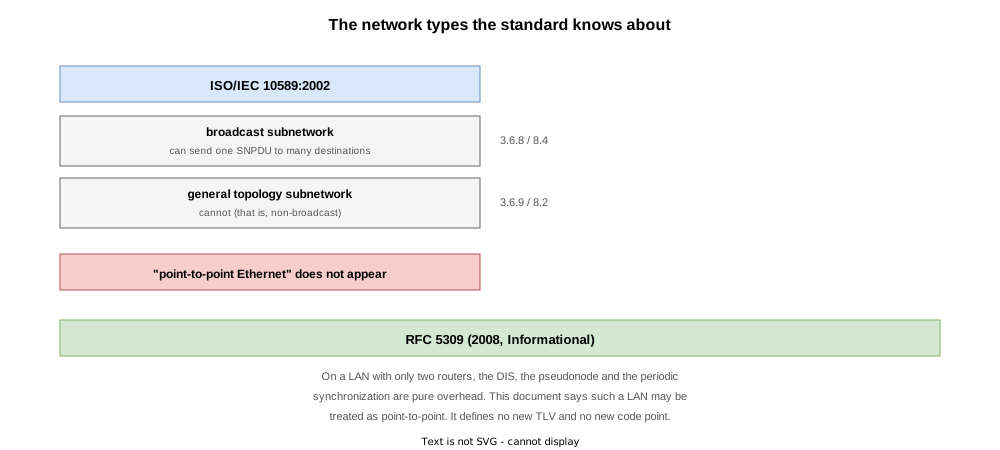
Clauses 3.6.8 and 3.6.9 of ISO/IEC 10589:2002 define these two.
| Name | Definition | Clause with the procedures |
|---|---|---|
| broadcast subnetwork | A subnetwork supporting an arbitrary number of End and Intermediate systems that is additionally capable of transmitting a single SNPDU to a subset of these systems in response to a single SN_UNITDATA request (3.6.8) | 8.4 |
| general topology subnetwork | A subnetwork supporting an arbitrary number of End and Intermediate systems but without the convenient multi-destination facility a broadcast subnetwork has (3.6.9) | 8.2 |
The opening of clause 8 says the only two circuit types the Subnetwork Independent Functions recognise are broadcast and general topology.
There is no category for “point-to-point Ethernet”. Ethernet is a broadcast subnetwork, and the standard puts it under 8.4 (DIS and pseudonodes).
RFC 5309: Treating a Two-Router LAN as Point-to-Point
The point-to-point used in practice comes from RFC 5309, “Point-to-Point Operation over LAN in Link State Routing Protocols” (2008, Informational).
Its argument is that a LAN with only two routers has no reason to be treated as broadcast, and it gives three advantages:
- No designated router is involved
- No pseudonode appears in the link state database
- For IS-IS specifically, there is also no periodic database synchronization
RFC 5309 defines no new TLV and no new code point. It is a configuration convention that runs the existing point-to-point procedures over LAN media.
For the destination MAC, clause 4.1 of the RFC says AllISs, AllL1ISs and AllL2ISs as defined in ISO 10589 can all be used, and recommends AllISs — the 09:00:2B:00:00:05 that Table 9 of ISO/IEC 10589:2002 describes as “used by ISO 9542” (IS-IS Packet Types and Header Format). Clause 4.5 adds that a point-to-point circuit receiving LAN hellos, or a LAN circuit receiving point-to-point hellos, MUST discard them — which is why a one-sided configuration forms no adjacency.
What Changes

The same two routers on the same cable behave differently depending on this one setting.
| Item | broadcast (default) | point-to-point |
|---|---|---|
| IIH used | LAN Level 1 / Level 2 (PDU Type 15 / 16) | Point-to-Point (PDU Type 17) |
| Destination MAC | 01:80:C2:00:00:14 / 01:80:C2:00:00:15 | 09:00:2B:00:00:05 |
| Number of IIHs | One per level | A single type covering both levels |
| DIS election | yes | no |
| Pseudonode LSP | yes | no |
| Periodic CSNP | sent by the DIS | none |
| Two-way confirmation | TLV 6 (IS Neighbours) | TLV 240 (three-way, RFC 5303) |
What this article checks is that they all arrive together, or all disappear together. The IIH formats are covered in IS-IS Packet Types and Header Format, two-way confirmation in IS-IS Adjacency Formation and States, and the DIS in IS-IS DIS and the Pseudonode.
Verification on Real Equipment
The test environment

Only two routers on an Ethernet segment (10.1.0.0/24), the case RFC 5309 addresses. Both are in area 49.0001 and level-1-2; the only change is whether point-to-point is present.
| Router | NET | LAN IP |
|---|---|---|
| R1 | 49.0001.0010.0100.1001.00 | 10.1.0.1 |
| R2 | 49.0001.0020.0200.2002.00 | 10.1.0.2 |
The test STEPs
| STEP | Action | Purpose |
|---|---|---|
| 0 | Both sides broadcast (default) | Measure the state with a DIS, a pseudonode and periodic CSNPs |
| 1 | Set only R2 to point-to-point | What happens when just one side is changed |
| 2 | Both sides point-to-point | Confirm all three disappear together, and compare the traffic |
| 3 | Both sides back to broadcast (final state) | Same as the initial state |
The Default Is Broadcast (STEP 0)
  Circuit Type:             level-1-2
  Media Type:               LAN
  Circuit Number:           1
  Last IIH Received:        08:01:52 (0.60 sec ago), 1497 octets
  Last PDU Rejected:        07:59:55 (00:01:56 ago), 76 octets, L2 LSP, Wrong Adjacency State
  Last IIH Sent:            08:01:46 (6.28 sec ago), 1497 octets

  IPv4 BFD:                 Disabled
  IPv6 BFD:                 Disabled

  Level-1
    Adjacency Count:        1
    Adjacency Flaps:        0
    LAN ID:                 R2.01
    Priority (Local/DIS):   64/64
    Next LAN IIH in:        3 s
    LSP Pacing Interval:    33 ms
    PSNP Entry Queue Size:  0
    Hello Interval:         10 s
    Hello Multiplier:       3
  Level-2
    Adjacency Count:        1
    Adjacency Flaps:        0
    LAN ID:                 R2.01
    Priority (Local/DIS):   64/64
    Next LAN IIH in:        3 s
    LSP Pacing Interval:    33 ms
    PSNP Entry Queue Size:  0
    Hello Interval:         10 s
    Hello Multiplier:       3
Media Type: LAN: with nothing configured, Ethernet is treated as broadcast. LAN ID and Priority (Local/DIS) appear per level, and a DIS (R2) has been elected. Last PDU Rejected records an LSP that arrived at 07:59:55, before the adjacency came up; nothing is wrong at this point.
IS-IS 1 (Level-1) Link State Database
LSPID                 LSP Seq Num  LSP Checksum  LSP Holdtime/Rcvd  ATT/P/OL
R1.00-00            * 0x00000005   0x1506        1085 /*            0/0/0
R2.00-00              0x00000005   0x955a        1087 /1200         0/0/0
R2.01-00              0x00000002   0xac86        1087 /1200         0/0/0

 Total Level-1 LSP count: 3     Local Level-1 LSP count: 1

IS-IS 1 (Level-2) Link State Database
LSPID                 LSP Seq Num  LSP Checksum  LSP Holdtime/Rcvd  ATT/P/OL
R1.00-00            * 0x00000007   0x7603        1089 /*            0/0/0
R2.00-00              0x00000007   0xfb56        1090 /1200         0/0/0
R2.01-00              0x00000002   0xac86        1087 /1200         0/0/0

 Total Level-2 LSP count: 3     Local Level-2 LSP count: 1
Two routers but three LSPs: R2.01-00 is the pseudonode LSP the DIS creates.
Changing Only One Side (STEP 1)

Only R2 is set to point-to-point.
router isis 1
 interface GigabitEthernet0/0/0/0
point-to-pointRP/0/RP0/CPU0:R1#show isis neighbors
Wed Sep 9 08:08:05.414 UTC
IS-IS 1 neighbors:
System Id Interface SNPA State Holdtime Type IETF-NSFThe adjacency is gone, and R2’s table is empty too.
With an MTU mismatch the larger-MTU side stays in Init (IS-IS Adjacency Formation and States); with a network type mismatch neither side can see the other. Each router states why.
  Circuit Type:             level-1-2
  Media Type:               LAN
  Circuit Number:           1
  Last IIH Received:        08:05:25 (00:02:39 ago), 1497 octets
  Last PDU Rejected:        08:07:56 (8.72 sec ago), 1497 octets, P2P IIH, P2P IIH on LAN Interface
Last IIH Sent: 08:08:04 (0.28 sec ago), 1497 octets Media Type: P2P
Circuit Number: 0
Extended Circuit Number: 0
Last IIH Received: 08:05:23 (00:02:59 ago), 1497 octets
Last PDU Rejected: 08:08:21 (2.19 sec ago), 1497 octets, L1 LAN IIH, LAN IIH on P2P Interface
Last IIH Sent: 08:08:23 (0.01 sec ago), 1497 octetsThe two reasons mirror each other.
| Router | Media Type | Reason for rejection |
|---|---|---|
| R1 | LAN | P2P IIH on LAN Interface (a P2P IIH arrived on a LAN interface) |
| R2 | P2P | LAN IIH on P2P Interface (a LAN IIH arrived on a P2P interface) |
Last IIH Received is frozen at a time before the change on both routers.
The capture shows the two of them endlessly exchanging IIHs that never match.
$ tshark -r isis-nwtype-mismatch.pcap -n -Y "isis.type == 15 || isis.type == 16 || isis.type == 17" \
    -T fields -e eth.src -e eth.dst -e isis.type | sort | uniq -c
  26 52:54:00:1f:66:bf	01:80:c2:00:00:14	15
  26 52:54:00:1f:66:bf	01:80:c2:00:00:15	16
   5 52:54:00:4b:d0:88	01:80:c2:00:00:14	15
   5 52:54:00:4b:d0:88	01:80:c2:00:00:15	16
23 52:54:00:4b:d0:88 09:00:2b:00:00:05 17| Column | Content |
|---|---|
| 1st | Packet count (uniq -c) |
| 2nd | Source MAC. 52:54:00:1f:66:bf is R1, 52:54:00:4b:d0:88 is R2 |
| 3rd | Destination MAC |
| 4th | PDU Type |
The five 15 and 16 frames from R2 predate the change. After that, R1 keeps sending 15 and 16 to 01:80:c2:00:00:14 / :15 while R2 sends 17 to 09:00:2b:00:00:05.
With an MTU mismatch the smaller side’s IIHs still arrive, so one end lingers in Init; with a network type mismatch neither router accepts a single IIH from the other.
Download the capture taken during the network type mismatch, STEP 1 (isis-nwtype-mismatch.pcap)Setting Both Sides to Point-to-Point (STEP 2)
R1 was set to point-to-point as well.
RP/0/RP0/CPU0:R1#show isis neighbors
Wed Sep  9 08:14:03.768 UTC

IS-IS 1 neighbors:
System Id      Interface        SNPA           State Holdtime Type IETF-NSF
R2             Gi0/0/0/0        *PtoP*         Up    27       L1L2 Capable

Total neighbor count: 1
The adjacency is back and SNPA reads *PtoP*. The interface display changes too.
  Circuit Type:             level-1-2
  Media Type:               P2P
  Extended Circuit Number:  3
  Level-1
    Adjacency Count:        1
  Level-2
    Adjacency Count:        1
LAN ID, Priority (Local/DIS) and Next LAN IIH in have vanished, replaced by Extended Circuit Number, because there is no DIS.
IS-IS 1 (Level-1) Link State Database
LSPID                 LSP Seq Num  LSP Checksum  LSP Holdtime/Rcvd  ATT/P/OL
R1.00-00            * 0x00000009   0xcc4b        919  /*            0/0/0
R2.00-00              0x00000008   0x3cd3        919  /1199         0/0/0

 Total Level-1 LSP count: 2     Local Level-1 LSP count: 1

IS-IS 1 (Level-2) Link State Database
LSPID                 LSP Seq Num  LSP Checksum  LSP Holdtime/Rcvd  ATT/P/OL
R1.00-00            * 0x0000000d   0x1e56        920  /*            0/0/0
R2.00-00              0x0000000b   0xfa76        920  /1200         0/0/0

 Total Level-2 LSP count: 2     Local Level-2 LSP count: 1
The pseudonode LSP R2.01-00 is gone and there are two LSPs per level.
How much traffic is saved
Roughly 130 seconds of steady state under each setting, side by side.
| PDU | broadcast (130 s) | point-to-point (132 s) |
|---|---|---|
| LAN Level 1 IIH (15) | 61 | — |
| LAN Level 2 IIH (16) | 60 | — |
| Point-to-Point IIH (17) | — | 30 |
| Level 1 CSNP (24) | 15 | 0 |
| Level 2 CSNP (25) | 15 | 0 |
| Total | 151 | 30 |
| pcap size | 188 KB | 46 KB |
The packet count falls to a fifth.
IIHs drop from 121 to 30 because broadcast sends a separate IIH per level while point-to-point uses one. CSNPs go to zero, as RFC 5309 says: no periodic database synchronization.
show isis trace shows the DIS election stopping at the moment of the change.
Sep  9 08:09:22.593 isis/1/det ... isis_dis_run_election:739  DIS_ELECTION_RESULT_NO_DIS L1 Gi0/0/0/0
Sep  9 08:09:22.593 isis/1/det ... isis_dis_run_election:719  DIS_RUN_ELECTION L2 Gi0/0/0/0
Sep 9 08:09:22.593 isis/1/det ... isis_dis_run_election:739 DIS_ELECTION_RESULT_NO_DIS L2 Gi0/0/0/0Which to Choose
If a LAN holds only two routers, use point-to-point. The DIS, the pseudonode LSP and the periodic CSNPs are pure overhead between two routers.
Configure it at both ends. One side alone means no adjacency, and the reason is visible only in Last PDU Rejected.
Do not use it with three or more routers on the segment; RFC 5309 is about the two-router case.
STEP 3 returned both sides to broadcast, matching the initial state.
Verification Config and show Output
At every STEP the following three files were collected per router. The verification config is the ..._run.txt file (final state: STEP 3).
| File | Content |
|---|---|
..._show.txt | show version / show interface description / show route / show route isis / show isis / show isis hostname / show isis interface / show isis interface brief / show isis neighbors / show isis neighbors detail / show isis database / show isis database detail / show isis topology / show isis adjacency / show isis adjacency detail / show isis adjacency-log / show isis trace all | include ELECT / show isis trace all | include PSEUDO / show isis spf-log / show isis lsp-log / show isis statistics / show cef |
..._log.txt | show logging narrowed to that STEP (STEP 0 holds the full history since boot) |
..._run.txt | show running-config at that STEP (that is, the verification config for the STEP) |
In the final configuration neither router has point-to-point.
STEP 0: both sides broadcast (default)
| Router | show output | syslog | running-config |
|---|---|---|---|
| R1 | show | log | run |
| R2 | show | log | run |
STEP 1: only R2 set to point-to-point
| Router | show output | syslog | running-config |
|---|---|---|---|
| R1 | show | log | run |
| R2 | show | log | run |
STEP 2: both sides point-to-point
| Router | show output | syslog | running-config |
|---|---|---|---|
| R1 | show | log | run |
| R2 | show | log | run |
STEP 3: both sides back to broadcast (final state)
| Router | show output | syslog | running-config |
|---|---|---|---|
| R1 | show | log | run |
| R2 | show | log | run |
| There are three capture files. |
Download the broadcast steady-state capture, STEP 0 (isis-nwtype-broadcast.pcap)
Download the network type mismatch capture, STEP 1 (isis-nwtype-mismatch.pcap)
Download the point-to-point steady-state capture, STEP 2 (isis-nwtype-p2p.pcap)
References
| Standard | Title | Summary |
|---|---|---|
| ISO/IEC 10589:2002 (Second Edition) | Intermediate System to Intermediate System intra-domain routeing information exchange protocol | The IS-IS specification itself. This article draws on 3.6.8 / 3.6.9 (the definitions of the network types), the opening of clause 8 (only two circuit types are recognised), 8.2 (point-to-point procedures) and 8.4 (broadcast procedures). |
| RFC 5309 | Point-to-Point Operation over LAN in Link State Routing Protocols | An Informational document setting out how a LAN with only two routers may be treated as point-to-point. It defines no new TLV and no new code point. Clause 4.1 recommends AllISs; 4.5 requires mismatched hello types to be discarded. |
| RFC 1142 | OSI IS-IS Intra-domain Routing Protocol | A republication of the ISO 10589 Draft Proposal (1990), now Historic. It must not be referenced in place of ISO/IEC 10589 (see RFC 7142). |
| RFC 7142 | Reclassification of RFC 1142 to Historic | States that references should be to ISO/IEC 10589:2002, Second Edition. |
| RFC 5303 | Three-Way Handshake for IS-IS Point-to-Point Adjacencies | Defines TLV 240, carried in point-to-point IIHs. |
| RFC 1195 | Use of OSI IS-IS for Routing in TCP/IP and Dual Environments | The extension that carries IP routes. |
Related Articles
- What is IS-IS
- IS-IS NSAP Addresses and the NET (System ID)
- IS-IS Multiple Area Addresses (Multihoming), Merging and Splitting Areas
- IS-IS Level 1 and Level 2 (the hierarchy)
- IS-IS Packet Types and Header Format
- IS-IS Adjacency Formation and States
- IS-IS DIS and the Pseudonode
- IS-IS Network Types (broadcast / point-to-point)
- IS-IS Metrics (narrow and wide)
- IS-IS Authentication (hello-password and lsp-password)
- IS-IS LSPs and the Link-State Database
- The Main IS-IS TLVs
- IS-IS Flooding and LSDB Synchronisation
- IS-IS SPF Computation and Route Selection
- IS-IS ECMP (Equal-Cost Multipath)
- The IS-IS ATT Bit and the Level 1 Default Route
- IS-IS Route Leaking and the Up/Down Bit
- IS-IS Route Summarization
- The IS-IS Overload Bit
- IS-IS IPv6 Support and Multi-Topology (TLV 236 / MT ID 2)
- IS-IS Hello and Holding Time
- IS-IS Convergence Timers (SPF / LSP Generation)
- IS-IS Flooding Timers (LSP Interval, Retransmission, CSNP / PSNP)
- IS-IS Link Failure and Path Switchover
- IS-IS Redistribution (connected / static)
- IS-IS Redistribution of BGP Routes