IS-IS NSAP Addresses and the NET (System ID)
IS-IS was standardised by ISO for CLNP, so even when it is used purely to carry IP routes, each router is configured with one ISO-style address. That address is an NSAP (Network Service Access Point), and the one that identifies the router itself is called the NET (Network Entity Title).
The biggest difference from an IP address is where it is attached.
| Item | IP address | NSAP (NET) |
|---|---|---|
| Attached to | Each interface (link based) | One per node (node based) |
| Length | Fixed 4 bytes (IPv4) | Variable, 8 to 20 bytes |
| Notation | Dotted decimal (192.168.1.24) | Dotted hexadecimal (49.0001.0010.0100.1001.00) |
What IS-IS uses to identify a node is the System ID inside the NSAP. It plays the role of the OSPF router ID, but it has nothing to do with IP addresses.
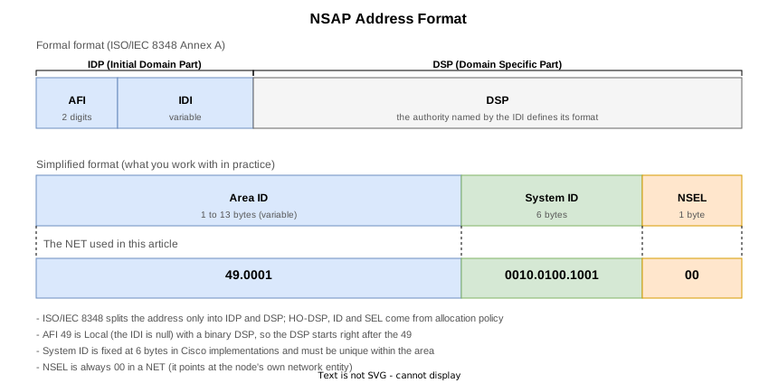
The NSAP address format
The formal format is defined in Annex A (normative) of ISO/IEC 8348, which splits the address in two (A.5.1.1). The edition referenced here is the third (2002), technically aligned with ITU-T X.213; ISO/IEC 10589:2002 normatively references the second edition (1996).
| Part | Name | Contents |
|---|---|---|
| IDP | Initial Domain Part | The AFI (Authority and Format Identifier) and the IDI (Initial Domain Identifier) |
| DSP | Domain Specific Part | Allocated by the authority the IDI points to. ISO/IEC 8348 does not subdivide the DSP any further |
The “HO-DSP”, “ID” and “SEL” seen in practice are not ISO/IEC 8348 terms; they come from allocation policies such as GOSIP.
ISO/IEC 10589:2002 notes in Figure 4 that IDP, DSP, AFI and IDI are drawn only to show the correspondence and are not explicitly used by this protocol, and it works with the address split into three parts (7.1.1). That simplified format is what is used in practice.
| Field | Length | Contents |
|---|---|---|
| Area ID | 1 to 13 bytes (variable) | Starts at the AFI and runs to just before the System ID. It is the area this router belongs to. 7.1.2 defines it as the entire high-order part excluding the ID and SEL fields |
| System ID | 6 bytes (Cisco implementation) | The value that identifies the node. 7.1.3.2 makes it 1 to 8 bytes, with a single length chosen per routeing domain |
| NSEL | 1 byte | The NSAP selector. Always 00 in a NET (the architectural constant IntradomainRouteingSelector = 0 in Table 2) |
A whole NSAP is at most 20 bytes (ISO/IEC 8348 A.5.4). For IP routing, the common choice is 10 bytes: 1 for the AFI, 2 for the area, 6 for the System ID and 1 for the NSEL.
49.0001.0010.0100.1001.00
\_____/ \____________/ \/
Area ID    System ID  NSEL
The Area ID is 3 bytes (the AFI 49 plus the area number 0001), the System ID 6 bytes and the NSEL 1 byte,
10 bytes in total.
The AFI and 49
The Area ID starts with the AFI, which per A.5.1.1.1 of ISO/IEC 8348 indicates four things.
- The format of the IDI
- The authority that allocates IDI values
- Whether leading zeros in the IDI are significant
- The abstract syntax of the DSP
The allocation of AFI values is given in Table A.4 of the same standard.
| IDI format | Decimal | Binary | ISO/IEC 646 character | National character |
|---|---|---|---|---|
| X.121 (public data networks) | 36, 52 | 37, 53 | — | — |
| ISO DCC (country code) | 38 | 39 | — | — |
| F.69 (telex) | 40, 54 | 41, 55 | — | — |
| E.163 (public telephone) | 42, 56 | 43, 57 | — | — |
| E.164 (ISDN) | 44, 58 | 45, 59 | — | — |
| ISO 6523 ICD (organisation code) | 46 | 47 | — | — |
| IANA ICP | 34 | 35 | — | — |
| ITU-T IND | 76 | 77 | — | — |
| Local | 48 | 49 | 50 | 51 |
The rows with two values exist because of the third item (whether leading zeros are significant). A variable-length IDI is padded to its maximum length in the binary encoding, so padding zeros have to be told apart from meaningful ones: the lower value means the IDI does not start with zero, the higher value means it does (A.5.2.1.2).
49 is the Local format with a binary DSP. Local has no IDI (it is null), so the IDP is just the AFI
and the DSP starts right after 49 (A.5.2.1.2.9). The maximum Local DSP in binary is 19 octets
(Table A.5), which with the one AFI octet comes to exactly 20.
“Local means private use” is not the standard’s wording. The note in Table A.4 says it exists so that OSI and
non-OSI address schemes can coexist. That said, no IDI means no higher authority guaranteeing uniqueness,
so such addresses may well be duplicated outside one organisation. Since IS-IS is an IGP and its routes do
not leave the AS, 49 is good enough for IP routing.
System ID uniqueness is per area for Level 1 and per domain for Level 2
The System ID is a 6-byte value, and 7.1.4 of ISO/IEC 10589:2002 lists three requirements.
| Standard | Requirement | Scope |
|---|---|---|
| 7.1.4 a)2) | No two systems (IS or ES) in an area may use the same ID value | Per area |
| 7.1.4 b)1) | No two Level 2 ISs in a routeing domain can have the same ID value | Per domain |
| 7.1.4 a)3) | Every system in the domain uses the same ID length | Per domain |
That a)2) is per area matters. Two Level 1 routers in different areas may, as far as the standard goes, share a System ID. Level 1 LSPs never leave their area, so no identifier collides inside any single LSDB. In practice the ID is still kept unique domain-wide, because hostname displays and any future merging of areas would otherwise become confusing.
Cisco implementations use a fixed 6-byte System ID (the IOS XR configuration guide states that each router is represented by a 6-byte hexadecimal system ID). The value itself is free, but a common practice is to derive it mechanically from a loopback address.
Step 1. Pad each octet to three digits
        192.168.1.24  ->  192.168.001.024

Step 2. Split the 12 digits into three groups of four
        192168001024  ->  1921.6800.1024

Step 3. Add the Area ID and the NSEL to make a NET
        49.0001.1921.6800.1024.00
Because it comes from the same value as the BGP or MPLS-TE router ID, it is immediately clear which router an
LSP in show isis database belongs to. Some use a MAC address directly, but that changes when hardware is
replaced, so deriving it from a loopback is easier to operate.
The NSEL
The last byte is the NSEL (NSAP selector), which says which user of the network layer service should receive
the PDU. In a NET the NSEL is always 00, which designates the node’s own network entity.
IOS XR rejects a NET with anything else while parsing the command, as shown later.
Several area addresses, and merging or splitting areas
A router can be given several NETs, which is how areas are merged or split. 7.1.5 of ISO/IEC 10589:2002
permits an area to have several synonymous area addresses, and the limit is the management parameter
maximumAreaAddresses (all ISs shall support a value of at least 3). That value is carried in the
protocol’s PDUs and checked for agreement within an area: if it does not match, adjacencies can fail to
initialise or the area can be partitioned.
How several area addresses behave, and the procedure for merging and splitting areas, are covered in IS-IS Multiple Area Addresses (Multihoming), Merging and Splitting Areas.
Dynamic hostname (TLV 137)
A System ID is hard to read, so IS-IS advertises the hostname in TLV 137 of the LSP and show output
substitutes it (RFC 5301). It is enabled by default on
IOS XR and the mapping is visible with show isis hostname. The TLV itself is covered in
IS-IS Major TLVs.
Lab setup

Seven XRd 26.1.1 routers form three areas. The System IDs follow the loopback conversion rule.
| Router | is-type | NET | Lo0 |
|---|---|---|---|
| R1 | level-1 | 49.0001.0010.0100.1001.00 | 1.1.1.1/32 |
| R5 | level-1 | 49.0001.0050.0500.5005.00 | 5.5.5.5/32 |
| R2 | level-1-2 | 49.0001.0020.0200.2002.00 | 2.2.2.2/32 |
| R3 | level-1-2 | 49.0002.0030.0300.3003.00 | 3.3.3.3/32 |
| R4 | level-1 | 49.0002.0040.0400.4004.00 | 4.4.4.4/32 |
| R6 | level-1 | 49.0002.0060.0600.6006.00 | 6.6.6.6/32 |
| R7 | level-2-only | 49.0003.0070.0700.7007.00 | 7.7.7.7/32 |
There are two Level 1 routers in one area (R1, R5), two more in another (R4, R6), and three Level 2 routers on the backbone (R2, R3, R7), so that each of the three uniqueness requirements described above can be checked in a STEP of its own.
Overview of the STEPs
| STEP | Action | What it shows |
|---|---|---|
| 0 | Initial state | Level 1 adjacencies inside an area, Level 2 across areas |
| 1 | R2’s Area ID to 49.0009 | Only the Level 1 adjacencies go down |
| 2 | R2’s Area ID restored | Recovery |
| 3 | R5’s System ID set to R1’s | What a duplicate inside one area does |
| 4 | R5 restored | Recovery |
| 5 | R7’s System ID set to R2’s | What a Level 2 duplicate across the domain does |
| 6 | R7 restored | Recovery |
| 7 | R6’s System ID set to R1’s | That two Level 1 routers in different areas are fine |
| 8 | R6 restored (final state) | Same as the initial state |
The sections below are grouped by what they show rather than by STEP order.
A Level 1 adjacency needs a matching Area ID
A Level 1 adjacency requires at least one area address in common; a Level 2 adjacency forms even when the areas differ. R2 and R3 in the initial state show both cases at once.
RP/0/RP0/CPU0:R2#show isis neighbors
Sun Sep 27 18:08:39.590 UTC

IS-IS 1 neighbors:
System Id      Interface        SNPA           State Holdtime Type IETF-NSF
R1             Gi0/0/0/0        *PtoP*         Up    28       L1   Capable
R5             Gi0/0/0/2        *PtoP*         Up    23       L1   Capable
R3             Gi0/0/0/1        *PtoP*         Up    26       L2   Capable

Total neighbor count: 3RP/0/RP0/CPU0:R3#show isis neighbors
Sun Sep 27 18:09:04.617 UTC
IS-IS 1 neighbors:
System Id Interface SNPA State Holdtime Type IETF-NSF
R6 Gi0/0/0/2 *PtoP* Up 26 L1 Capable
R4 Gi0/0/0/1 *PtoP* Up 21 L1 Capable
R2 Gi0/0/0/0 *PtoP* Up 24 L2 Capable
R7 Gi0/0/0/3 *PtoP* Up 27 L2 Capable
Total neighbor count: 4R2 is L1 with R1 and R5 in the same area and L2 with R3 in another. R3 is the same, and with the
level-2-only R7 it is L2 only.
Changing R2’s Area ID to 49.0009 puts the reason in R1’s syslog.
RP/0/RP0/CPU0:Sep 27 18:11:20.558 UTC: isis[1003]: %ROUTING-ISIS-5-ADJCHANGE : ISIS (1): Adjacency to 49.0001.0020.0200.2002 (GigabitEthernet0/0/0/0) (L1) Down, Area addr/level differ What the IIH carries is the Area address TLV (TLV 1). Only that value changes across the edit.
    Area address(es) (t=1, l=4)
        Type: 1
        Length: 4
        Area address (3): 49.0001
Area address(es) (t=1, l=4)
Type: 1
Length: 4
Area address (3): 49.0009No.2 of the same capture shows R2 withdrawing its own Level 1 LSP from the old area.
ISO 10589 ISIS Link State Protocol Data Unit
    PDU length: 40
    Remaining lifetime: 0
    LSP-ID: 0020.0200.2002.00-00
    Sequence number: 0x00000006
    [Checksum: [missing]]
    [Checksum Status: Not present]
    Type block(0x0b): Partition Repair:0, Attached bits:1, Overload bit:0, IS type:3
        0... .... = Partition Repair: Not supported
        .000 1... = Attachment: 1
            .0.. .... = Error metric: Not set
            ..0. .... = Expense metric: Not set
            ...0 .... = Delay metric: Not set
            0... .... = Default metric: Not set
        .... .0.. = Overload bit: Not set
        .... ..11 = Type of Intermediate System: Level 2 (3)
    Purge Originator ID (t=13, l=7)
        Type: 13
        Length: 7
        Number of System IDs: 1
System ID: 0020.0200.2002An LSP with Remaining lifetime: 0 is a purge. Clause 7.3.16.4 of ISO/IEC 10589:2002 says a zero-lifetime LSP
propagates with only its header retained. The Purge Originator ID TLV (TLV 13) is not in the standard;
it was added by RFC 6232.
What happens when System IDs collide
Results of ping (20 packets) from seven routers in each STEP. The damage is confined exactly to the scope
of each requirement.
| STEP | R1→R4 | R1→R6 | R1→R7 | R1→R5 | R4→R1 | R5→R4 | R6→R1 | R7→R2 |
|---|---|---|---|---|---|---|---|---|
| 0 (initial state) | 100% | 100% | 100% | 100% | 100% | 100% | 100% | 100% |
| 1 (R2’s Area ID changed) | 0% | 0% | 0% | 0% | 0% | 0% | 0% | 100% |
| 3 (duplicate inside one area) | 0% | 0% | 0% | 0% | 0% | 100% | 0% | 100% |
| 5 (Level 2 duplicate) | 0% | 0% | 0% | 100% | 0% | 0% | 0% | 0% |
| 7 (Level 1 in different areas) | 100% | 100% | 100% | 100% | 100% | 100% | 100% | 100% |
A duplicate inside one area (STEP 3)
Setting R5’s System ID to R1’s 0010.0100.1001 breaks what R2, adjacent to both, sees.
RP/0/RP0/CPU0:R2#show isis neighbors
Sun Sep 27 18:29:48.357 UTC

IS-IS 1 neighbors:
System Id      Interface        SNPA           State Holdtime Type IETF-NSF
R5             Gi0/0/0/0        *PtoP*         Up    22       L1   Capable
R5             Gi0/0/0/2        *PtoP*         Up    21       L1   Capable
R3             Gi0/0/0/1        *PtoP*         Up    21       L2   Capable

Total neighbor count: 3RP/0/RP0/CPU0:R2#show isis database
Sun Sep 27 18:29:49.297 UTC
IS-IS 1 (Level-1) Link State Database
LSPID LSP Seq Num LSP Checksum LSP Holdtime/Rcvd ATT/P/OL
R5.00-00 0x00000008 0x5c03 911 /1200 0/0/0
R2.00-00 * 0x00000004 0xa1ae 909 /* 1/0/0
Total Level-1 LSP count: 2 Local Level-1 LSP count: 1
IS-IS 1 (Level-2) Link State Database
LSPID LSP Seq Num LSP Checksum LSP Holdtime/Rcvd ATT/P/OL
R2.00-00 * 0x0000000c 0xf720 911 /* 0/0/0
R3.00-00 0x0000000e 0xfc50 557 /1199 0/0/0
R7.00-00 0x00000005 0x163b 883 /1200 0/0/0
Total Level-2 LSP count: 3 Local Level-2 LSP count: 1RP/0/RP0/CPU0:R1#show isis database
Sun Sep 27 18:29:23.808 UTC
IS-IS 1 (Level-1) Link State Database
LSPID LSP Seq Num LSP Checksum LSP Holdtime/Rcvd ATT/P/OL
R1.00-00 * 0x00000007 0xdab6 583 /* 0/0/0
R2.00-00 0x00000004 0xa1ae 934 /1200 1/0/0
Total Level-1 LSP count: 2 Local Level-1 LSP count: 1R2’s neighbour table shows R5 as the peer on both interfaces: the hostname comes from TLV 137 in the LSP,
and one System ID can only carry one name. Its Level 1 LSDB holds only R5.00-00, so R1’s LSP is gone.
An LSP ID is built from the System ID, so only one LSP per ID can be held and the later arrival replaces the
earlier one.
R1’s own LSDB, meanwhile, still holds R1.00-00 *, so R1 sees nothing wrong — while every packet towards
R1 is dropped (the 0% above). R1’s prefixes have disappeared from the area’s LSDB, and
the broken router itself cannot tell.
A Level 2 duplicate across the domain (STEP 5)
Setting R7’s System ID to R2’s does the same thing in the Level 2 subdomain. R7 and R2 are not adjacent, so the collision surfaces on R3, which is adjacent to both.
RP/0/RP0/CPU0:R3#show isis neighbors
Sun Sep 27 18:43:42.899 UTC

IS-IS 1 neighbors:
System Id      Interface        SNPA           State Holdtime Type IETF-NSF
R6             Gi0/0/0/2        *PtoP*         Up    29       L1   Capable
R4             Gi0/0/0/1        *PtoP*         Up    29       L1   Capable
R7             Gi0/0/0/0        *PtoP*         Up    29       L2   Capable
R7             Gi0/0/0/3        *PtoP*         Up    27       L2   Capable

Total neighbor count: 4RP/0/RP0/CPU0:R3#show isis database
Sun Sep 27 18:43:43.937 UTC
IS-IS 1 (Level-1) Link State Database
LSPID LSP Seq Num LSP Checksum LSP Holdtime/Rcvd ATT/P/OL
R3.00-00 * 0x0000000b 0x8f7e 824 /* 1/0/0
R4.00-00 0x00000007 0x2aac 792 /1200 0/0/0
R6.00-00 0x00000008 0x126b 789 /1200 0/0/0
Total Level-1 LSP count: 3 Local Level-1 LSP count: 1
IS-IS 1 (Level-2) Link State Database
LSPID LSP Seq Num LSP Checksum LSP Holdtime/Rcvd ATT/P/OL
R7.00-00 0x0000000f 0xf7f9 883 /1200 0/0/0
R3.00-00 * 0x00000010 0xb995 881 /* 0/0/0
Total Level-2 LSP count: 2 Local Level-2 LSP count: 1R2’s LSP disappears from the Level 2 LSDB. R2 is the only router joining area 49.0001 to the backbone, so everything crossing an area boundary fails. R1 to R5, inside the same area, stays at 100%, which shows the damage is limited to the Level 2 subdomain.
Two Level 1 routers in different areas are fine (STEP 7)
R6 (Level 1 in area 49.0002) is given the same System ID as R1 (Level 1 in area 49.0001). The requirement is per area, so this is not a violation.
RP/0/RP0/CPU0:R2#show isis hostname
Sun Sep 27 18:54:32.990 UTC

IS-IS 1 hostnames
Level  System ID      Dynamic Hostname
 1     0010.0100.1001 R1
 1,2 * 0020.0200.2002 R2
 2     0070.0700.7007 R7
 1     0050.0500.5005 R5
2 0030.0300.3003 R3RP/0/RP0/CPU0:R3#show isis hostname
Sun Sep 27 18:55:00.015 UTC
IS-IS 1 hostnames
Level System ID Dynamic Hostname
1 0010.0100.1001 R6
2 0020.0200.2002 R2
2 0070.0700.7007 R7
1,2 * 0030.0300.3003 R3
1 0040.0400.4004 R4The same System ID 0010.0100.1001 maps to R1 on R2 and to R6 on R3. Level 1 LSPs never leave their
area, so the identifier collides in neither LSDB, and all eight ping paths stay at 100%.
The NSEL will not take anything but 00
Trying to configure a NET whose NSEL is not 00 is rejected by IOS XR while it parses the command.
RP/0/RP0/CPU0:R1(config-isis)#net 49.0001.0010.0100.1001.01

                                  ^
% Invalid input detected at '^' marker.
RP/0/RP0/CPU0:R1(config-isis)#abort

RP/0/RP0/CPU0:R1#show running-config router isis

Sun Sep 27 18:05:28.787 UTC
router isis 1
 is-type level-1
 net 49.0001.0010.0100.1001.00
 log adjacency changes
The caret (^) points at the NSEL. The show running-config router isis after abort still shows the
original NET, which proves it never even entered the candidate configuration.
Configuring and checking the NET
IOS XR configures it with the net command under router isis.
RP/0/RP0/CPU0:R1#show running-config router isis
Sun Sep 27 18:08:15.829 UTC
router isis 1
 is-type level-1
 net 49.0001.0010.0100.1001.00
 log adjacency changes
 address-family ipv4 unicast
  metric-style wide
 !
 interface Loopback0
  passive
  address-family ipv4 unicast
  !
 !
 interface GigabitEthernet0/0/0/0
  point-to-point
  address-family ipv4 unicast
  !
 !
!
What was configured is visible with show isis.
RP/0/RP0/CPU0:R2#show isis
Sun Sep 27 18:08:38.882 UTC

IS-IS Router: 1
  System Id: 0020.0200.2002
  Hostname: R2
  IS Levels: level-1-2
  Manual area address(es):
    49.0001
  Routing for area address(es):
    49.0001
Multi-Instance Id: 0| Field | Meaning |
|---|---|
| System Id | The System ID taken from the NET. This becomes the LSP identifier |
| IS Levels | The levels this router runs (what is-type was set to) |
| Manual area address(es) | The Area IDs of the configured NETs. Several NETs make several lines |
| Routing for area address(es) | The areas actually being routed for. Normally the same as above |
Verification configs and show output
Collected from all seven routers in every STEP. The verification config is the ..._run.txt file
(the final state is the one from STEP 8).
| File | Contents |
|---|---|
..._show.txt | The show set: show version / show interface / show route / show route summary / show cef / show isis / show isis hostname / show isis neighbors detail / show isis adjacency-log / show isis database detail / show isis database level 1 / level 2 / show isis topology / show isis route and more (30 to 32 commands depending on the role) |
..._ping.txt | ping (20 packets) and traceroute |
..._clear.txt | Record of the interface counters cleared in that STEP |
..._commit.cfg | Only the configuration committed in that STEP (absent for STEP 0, which changes nothing) |
..._log.txt | show logging limited to the range of that STEP |
..._run.txt | show running-config at that STEP (the verification config for the STEP) |
..._trace.txt | show isis trace standard | include ADJ (adjacency state changes) |
STEP 0: Initial state
| Router | show | ping / traceroute | clear | Config committed | syslog | running-config | trace |
|---|---|---|---|---|---|---|---|
| R1 | show | ping | clear | — | log | run | trace |
| R2 | show | — | clear | — | log | run | trace |
| R3 | show | — | clear | — | log | run | trace |
| R4 | show | ping | clear | — | log | run | trace |
| R5 | show | ping | clear | — | log | run | trace |
| R6 | show | ping | clear | — | log | run | trace |
| R7 | show | ping | clear | — | log | run | trace |
STEP 1: R2’s Area ID changed to 49.0009
| Router | show | ping / traceroute | clear | Config committed | syslog | running-config | trace |
|---|---|---|---|---|---|---|---|
| R1 | show | ping | clear | — | log | run | trace |
| R2 | show | — | clear | commit | log | run | trace |
| R3 | show | — | clear | — | log | run | trace |
| R4 | show | ping | clear | — | log | run | trace |
| R5 | show | ping | clear | — | log | run | trace |
| R6 | show | ping | clear | — | log | run | trace |
| R7 | show | ping | clear | — | log | run | trace |
STEP 2: R2’s Area ID restored to 49.0001
| Router | show | ping / traceroute | clear | Config committed | syslog | running-config | trace |
|---|---|---|---|---|---|---|---|
| R1 | show | ping | clear | — | log | run | trace |
| R2 | show | — | clear | commit | log | run | trace |
| R3 | show | — | clear | — | log | run | trace |
| R4 | show | ping | clear | — | log | run | trace |
| R5 | show | ping | clear | — | log | run | trace |
| R6 | show | ping | clear | — | log | run | trace |
| R7 | show | ping | clear | — | log | run | trace |
STEP 3: R5’s System ID set to R1’s (duplicate inside one area)
| Router | show | ping / traceroute | clear | Config committed | syslog | running-config | trace |
|---|---|---|---|---|---|---|---|
| R1 | show | ping | clear | — | log | run | trace |
| R2 | show | — | clear | — | log | run | trace |
| R3 | show | — | clear | — | log | run | trace |
| R4 | show | ping | clear | — | log | run | trace |
| R5 | show | ping | clear | commit | log | run | trace |
| R6 | show | ping | clear | — | log | run | trace |
| R7 | show | ping | clear | — | log | run | trace |
STEP 4: R5’s System ID restored
| Router | show | ping / traceroute | clear | Config committed | syslog | running-config | trace |
|---|---|---|---|---|---|---|---|
| R1 | show | ping | clear | — | log | run | trace |
| R2 | show | — | clear | — | log | run | trace |
| R3 | show | — | clear | — | log | run | trace |
| R4 | show | ping | clear | — | log | run | trace |
| R5 | show | ping | clear | commit | log | run | trace |
| R6 | show | ping | clear | — | log | run | trace |
| R7 | show | ping | clear | — | log | run | trace |
STEP 5: R7’s System ID set to R2’s (duplicate across the domain at Level 2)
| Router | show | ping / traceroute | clear | Config committed | syslog | running-config | trace |
|---|---|---|---|---|---|---|---|
| R1 | show | ping | clear | — | log | run | trace |
| R2 | show | — | clear | — | log | run | trace |
| R3 | show | — | clear | — | log | run | trace |
| R4 | show | ping | clear | — | log | run | trace |
| R5 | show | ping | clear | — | log | run | trace |
| R6 | show | ping | clear | — | log | run | trace |
| R7 | show | ping | clear | commit | log | run | trace |
STEP 6: R7’s System ID restored
| Router | show | ping / traceroute | clear | Config committed | syslog | running-config | trace |
|---|---|---|---|---|---|---|---|
| R1 | show | ping | clear | — | log | run | trace |
| R2 | show | — | clear | — | log | run | trace |
| R3 | show | — | clear | — | log | run | trace |
| R4 | show | ping | clear | — | log | run | trace |
| R5 | show | ping | clear | — | log | run | trace |
| R6 | show | ping | clear | — | log | run | trace |
| R7 | show | ping | clear | commit | log | run | trace |
STEP 7: R6’s System ID set to R1’s (two Level 1 routers in different areas)
| Router | show | ping / traceroute | clear | Config committed | syslog | running-config | trace |
|---|---|---|---|---|---|---|---|
| R1 | show | ping | clear | — | log | run | trace |
| R2 | show | — | clear | — | log | run | trace |
| R3 | show | — | clear | — | log | run | trace |
| R4 | show | ping | clear | — | log | run | trace |
| R5 | show | ping | clear | — | log | run | trace |
| R6 | show | ping | clear | commit | log | run | trace |
| R7 | show | ping | clear | — | log | run | trace |
STEP 8: R6’s System ID restored (final state)
| Router | show | ping / traceroute | clear | Config committed | syslog | running-config | trace |
|---|---|---|---|---|---|---|---|
| R1 | show | ping | clear | — | log | run | trace |
| R2 | show | — | clear | — | log | run | trace |
| R3 | show | — | clear | — | log | run | trace |
| R4 | show | ping | clear | — | log | run | trace |
| R5 | show | ping | clear | — | log | run | trace |
| R6 | show | ping | clear | commit | log | run | trace |
| R7 | show | ping | clear | — | log | run | trace |
Packet captures were taken per STEP on three links.
| STEP | R1-R2 (Level 1) | R2-R3 (Level 2) | R3-R7 (Level 2) |
|---|---|---|---|
| 0 | pcap | pcap | pcap |
| 1 | pcap | pcap | pcap |
| 2 | pcap | pcap | pcap |
| 3 | pcap | pcap | pcap |
| 4 | pcap | pcap | pcap |
| 5 | pcap | pcap | pcap |
| 6 | pcap | pcap | pcap |
| 7 | pcap | pcap | pcap |
| 8 | pcap | pcap | pcap |
References
| Standard | Title | Summary |
|---|---|---|
| ISO/IEC 10589:2002 (second edition) | Intermediate System to Intermediate System intra-domain routeing information exchange protocol | 7.1.1 (with the note on Figure 4) and 7.1.2 for the address structure, 7.1.3.2 for the structure of the ID and SEL fields, 7.1.4 for the uniqueness requirements (a)2), b)1), a)3)), 7.1.5 for several area addresses and maximumAreaAddresses, 7.3.16.4 for purging an LSP, and Table 2 for the architectural constants. |
| ISO/IEC 8348:2002 (third edition) | Information technology — Open Systems Interconnection — Network service definition | The NSAP address format: A.5.1.1 of Annex A (normative) for IDP / DSP, A.5.2.1.1 and Table A.4 for AFI allocation, A.5.2.1.2 per IDI format (Local is A.5.2.1.2.9), A.5.4 for the 20-octet maximum, and Table A.5 for maximum DSP lengths. The edition technically aligned with ITU-T X.213. |
| RFC 6232 | Purge Originator Identification TLV for IS-IS | TLV 13, which puts the System ID of the purging router into a purged LSP. |
| RFC 1195 | Use of OSI IS-IS for Routing in TCP/IP and Dual Environments | The extension that carries IP routes in IS-IS (Integrated IS-IS). |
| RFC 5301 | Dynamic Hostname Exchange Mechanism for IS-IS | TLV 137, which maps a hostname to a System ID. |
| RFC 7142 | Reclassification of RFC 1142 to Historic | States that RFC 1142 is a republication of the ISO 10589 Draft Proposal, differs substantially from the final text, and must not be referenced in its place. |
Related articles
- What is IS-IS
- IS-IS NSAP Addresses and the NET (System ID)
- IS-IS Multiple Area Addresses (Multihoming), Merging and Splitting Areas
- IS-IS Level 1 and Level 2 (the hierarchy)
- IS-IS Packet Types and Header Format
- IS-IS Adjacency Formation and States
- IS-IS DIS and the Pseudonode
- IS-IS Network Types (broadcast / point-to-point)
- IS-IS Metrics (narrow and wide)
- IS-IS Authentication (hello-password and lsp-password)
- IS-IS LSPs and the Link-State Database
- The Main IS-IS TLVs
- IS-IS Flooding and LSDB Synchronisation
- IS-IS SPF Computation and Route Selection
- IS-IS ECMP (Equal-Cost Multipath)
- The IS-IS ATT Bit and the Level 1 Default Route
- IS-IS Route Leaking and the Up/Down Bit
- IS-IS Route Summarization
- The IS-IS Overload Bit
- IS-IS IPv6 Support and Multi-Topology (TLV 236 / MT ID 2)
- IS-IS Hello and Holding Time
- IS-IS Convergence Timers (SPF / LSP Generation)
- IS-IS Flooding Timers (LSP Interval, Retransmission, CSNP / PSNP)
- IS-IS Link Failure and Path Switchover
- IS-IS Redistribution (connected / static)
- IS-IS Redistribution of BGP Routes