IS-IS Packet Types and Header Format
IS-IS does everything from neighbour discovery to database synchronization with its own packets (What Is IS-IS). ISO/IEC 10589 calls them PDUs (Protocol Data Units); this article says “packet”.
What stands out is that the header is short and almost everything else is a TLV (Type-Length-Value). The common header is 8 bytes, followed by a per-type fixed part and the TLVs.
This article covers the nine packet types, the common header and the TLV mechanism, checked against Cisco IOS XR captures. A tshark listing of all nine types is included.
The Addresses and Encapsulation IS-IS Packets Use
IS-IS packets do not ride on IP; they sit directly in an Ethernet frame (What Is IS-IS).
| Item | Value |
|---|---|
| Encapsulation | Ethernet (IEEE 802.3) plus LLC (DSAP/SSAP = 0xFE, Control = 0x03) |
| Destination MAC | 01:80:C2:00:00:14 (AllL1ISs) / 01:80:C2:00:00:15 (AllL2ISs) on broadcast links; 09:00:2B:00:00:05 on links running as point-to-point |
| Where IS-IS starts | 0x83 at the front of the common header (Intradomain Routeing Protocol Discriminator) |
All three appear in Table 9 of ISO/IEC 10589:2002, but 09:00:2B:00:00:05 is described there as “AllIntermediateSystems — used by ISO 9542”, making it an ES-IS (ISO 9542) address. It is used for point-to-point over Ethernet because clause 4.1 of RFC 5309 recommends AllISs.
Because this article’s test uses both a broadcast link and a point-to-point link, all three were observed.
Packet Types
Packets fall into three categories, and clause 9.4 of ISO/IEC 10589:2002 lists exactly nine.
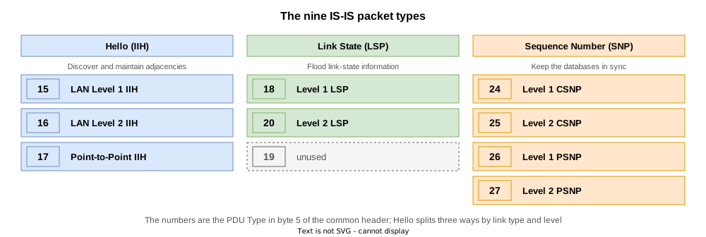
| Category | Packet | PDU Type | Role |
|---|---|---|---|
| Hello | LAN Level 1 IIH | 15 | Forms and maintains Level 1 adjacencies on a broadcast link |
| Hello | LAN Level 2 IIH | 16 | Forms and maintains Level 2 adjacencies on a broadcast link |
| Hello | Point-to-Point IIH | 17 | Forms and maintains adjacencies on a point-to-point link; the level is carried in the Circuit type field |
| Link State | Level 1 LSP | 18 | Distributes Level 1 link state |
| Link State | Level 2 LSP | 20 | Distributes Level 2 link state |
| Sequence Number | Level 1 CSNP | 24 | Shows the list of LSPs in the Level 1 database |
| Sequence Number | Level 2 CSNP | 25 | Shows the list of LSPs in the Level 2 database |
| Sequence Number | Level 1 PSNP | 26 | Requests missing Level 1 LSPs / acknowledges received ones |
| Sequence Number | Level 2 PSNP | 27 | Requests missing Level 2 LSPs / acknowledges received ones |
Mapped onto OSPF:
| OSPF | IS-IS |
|---|---|
| Hello (Type 1) | IIH (15 / 16 / 17) |
| DBD (Type 2) | CSNP (24 / 25) |
| LSR (Type 3) | PSNP (26 / 27) |
| LSU (Type 4) | LSP (18 / 20) |
| LSAck (Type 5) | PSNP (26 / 27) |
The PSNP does two jobs, request (LSR) and acknowledgement (LSAck), shown in PSNP (PDU Type 26 / 27). And Hello splits three ways by link type and level.
There is no PDU numbered 19.
The Common Header Format
All nine packet types begin with the same 8-byte header. Every field is one byte.
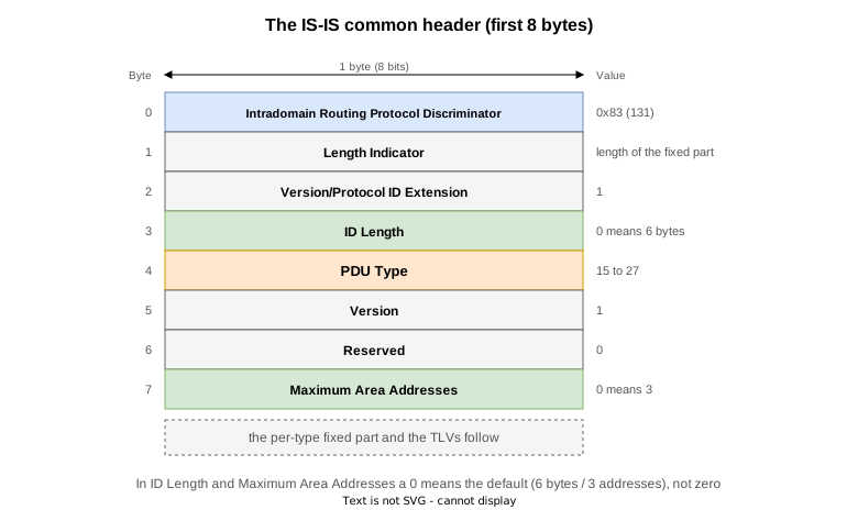
| Field | Length | Content |
|---|---|---|
| Intradomain Routeing Protocol Discriminator | 1 byte | The fixed value 0x83 (binary 10000011, decimal 131) identifying IS-IS. Table 2 of ISO/IEC 10589:2002 lists it as the architectural constant IntradomainRouteingPD; the value itself is assigned by ISO/TR 9577 (network-layer protocol identifiers) |
| Length Indicator | 1 byte | Length of the fixed header in bytes, TLVs excluded |
| Version/Protocol ID Extension | 1 byte | 1 |
| ID Length | 1 byte | Length of the System ID used in this routeing domain. 0 means 6 bytes; 1 to 8 mean that many bytes; 255 means length zero. Any other value is illegal |
| PDU Type | 1 byte | The low five bits (bits 1 to 5) give the packet type (15 to 27). The top three bits (6 to 8) are reserved, sent as zero and ignored on receipt |
| Version | 1 byte | 1 |
| Reserved | 1 byte | Unused. Sent as 0, ignored on receipt |
| Maximum Area Addresses | 1 byte | The number of area addresses permitted for this IS’s area. 1 to 254 are valid, and 0 is treated on receipt as 3 |
For ID Length and Maximum Area Addresses, 0 means the default (6 bytes / 3 addresses).
Clause 9.1 of ISO/IEC 10589:2002 numbers bits 1 to 8, bit 1 being the least significant.
The Length Indicator changes with the packet type: the 8-byte common header plus the per-type fixed part.
| Packet | Length Indicator | Breakdown (8-byte common header plus fixed part) |
|---|---|---|
| LAN IIH (15 / 16) | 27 | 8 + Circuit type 1 + Source ID 6 + Holding Time 2 + PDU Length 2 + Priority 1 + LAN ID 7 |
| Point-to-Point IIH (17) | 20 | 8 + Circuit type 1 + Source ID 6 + Holding Time 2 + PDU Length 2 + Local Circuit ID 1 |
| LSP (18 / 20) | 27 | 8 + PDU Length 2 + Remaining Lifetime 2 + LSP ID 8 + Sequence Number 4 + Checksum 2 + Type block 1 |
| CSNP (24 / 25) | 33 | 8 + PDU Length 2 + Source ID 7 + Start LSP ID 8 + End LSP ID 8 |
| PSNP (26 / 27) | 17 | 8 + PDU Length 2 + Source ID 7 |
How TLVs Work
Behind the common header and the per-type fixed part comes a run of TLVs (Type-Length-Value).
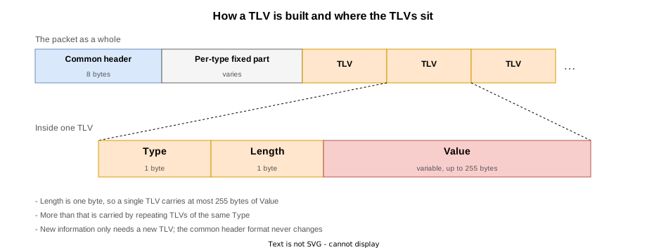
| Element | Length | Content |
|---|---|---|
| Type | 1 byte | A number saying what this TLV represents |
| Length | 1 byte | Length of the Value in bytes |
| Value | Variable | The content |
Because Length is one byte, a TLV carries at most 255 bytes; larger data repeats the same Type. ISO/IEC 10589:2002 says unrecognised CODEs are ignored, and for LSPs passed through unchanged (clause 9.8), so an unknown TLV does not break flooding.
The standard calls this run VARIABLE LENGTH FIELDS and labels the first byte CODE (clauses 9.5 to 9.13). Neither “TLV” nor “CLV” is the standard’s word, but this article uses TLV.
Something new is carried by adding a TLV. That is how IPv6 (RFC 5308) and segment routing were added. The main TLVs are covered in The Main IS-IS TLVs.
ISO/IEC 10589:2002 defines only CODEs 1 to 10 and 14; every other TLV in these captures was added by the IETF.
| TLV | Name | Source |
|---|---|---|
| 1 | Area Addresses | ISO/IEC 10589:2002 |
| 6 | IS Neighbours (6-byte MAC addresses) | ISO/IEC 10589:2002. Appears only in a LAN IIH |
| 8 | Padding | ISO/IEC 10589:2002 |
| 9 | LSP Entries | ISO/IEC 10589:2002. Used by CSNP and PSNP |
| 14 | originatingLSPBufferSize | ISO/IEC 10589:2002 |
| 129 | Protocols Supported | RFC 1195 |
| 132 | IP Interface Address | RFC 1195 |
| 137 | Dynamic Hostname | RFC 5301 |
| 211 | Restart Signaling | RFC 5306 |
| 240 | Point-to-Point Adjacency State | RFC 5303 |
Verification on Real Equipment
The lab

To observe all nine types the lab contains both a broadcast segment and point-to-point links. Some packets only appear on a LAN (15, 16, 24), and a PSNP only appears as an acknowledgement on a point-to-point link.
| Router | NET | is-type | Links |
|---|---|---|---|
| R1 | 49.0001.0010.0100.1001.00 | level-1 | LAN only |
| R2 | 49.0001.0020.0200.2002.00 | (default = level-1-2) | LAN only |
| R3 | 49.0001.0030.0300.3003.00 | (default = level-1-2) | LAN plus the p2p to R4 |
| R4 | 49.0001.0040.0400.4004.00 | (default = level-1-2) | The p2p to R3 plus the p2p to R5 |
| R5 | 49.0002.0050.0500.5005.00 | (default = level-1-2) | The p2p to R4 only |
R1, R2 and R3 sit on a broadcast segment (10.0.0.0/24) in area 49.0001. R3-R4 is also point-to-point inside that area, and only R4-R5 crosses an area boundary.
The LAN interfaces are not configured as point-to-point. Left at the broadcast default, a DIS is elected and the LAN IIHs and CSNPs flow.
R3-R4 is kept inside one area so that the point-to-point link forms both a Level 1 and a Level 2 adjacency. That makes the Circuit type of the P2P IIH show both levels, and it makes the Level 1 and Level 2 PSNPs appear as acknowledgements.
RP/0/RP0/CPU0:R3#show isis neighbors
Tue Oct  6 00:54:26.102 UTC

IS-IS 1 neighbors:
System Id      Interface        SNPA           State Holdtime Type IETF-NSF
R1             Gi0/0/0/0        5254.004e.accf Up    29       L1   Capable
R2             Gi0/0/0/0        5254.006d.5fdf Up    24       L1L2 Capable
R4             Gi0/0/0/1        *PtoP*         Up    28       L1L2 Capable

Total neighbor count: 3
Gi0/0/0/0 carries two adjacencies because R1 is Level 1 only and R2 is Level 1-2. Gi0/0/0/1 (R4) is L1L2: it is point-to-point inside the same area, so both levels come up. The SNPA column holds the neighbour’s MAC address on the LAN and *PtoP* on the point-to-point links, where no MAC address is needed because there is only one neighbour.
show isis interface brief shows the difference too.
RP/0/RP0/CPU0:R3#show isis interface brief
Tue Oct  6 00:54:25.915 UTC

IS-IS 1 Interfaces
    Interface      All     Adjs    Adj Topos  Adv Topos  CLNS   MTU    Prio
                   OK    L1   L2    Run/Cfg    Run/Cfg                L1   L2
-----------------  ---  ---------  ---------  ---------  ----  ----  --------
Lo0                Yes    -    -      0/0        1/1     No       -    -    -
Gi0/0/0/0          Yes    2*   1*     1/1        1/1     Up    1497   64   64
Gi0/0/0/1          Yes    1    1      1/1        1/1     Up    1497    -    -
Prio is 64 on the LAN and - on the point-to-point links. The priority exists to elect a DIS, so a point-to-point link has no value for it. The * on an adjacency count marks this router as the DIS, and R3 is the DIS at both levels.
64 is the default of l1IntermediateSystemPriority and l2IntermediateSystemPriority in ISO/IEC 10589:2002. The election rule (8.4.5) is “the IS with the highest priority, and on a tie the highest MAC address”, so the tie here was broken by the MAC address. The IS-IS DIS and pseudonode covers it in detail.
The STEPs
| STEP | Change | What it shows |
|---|---|---|
| 0 | The initial state | The IIHs (15 / 16 / 17) and CSNPs (24 / 25) that flow steadily |
| 1 | process restart isis on all five | Resynchronising brings the LSPs (18 / 20) and PSNPs (26 / 27) |
| 2 | process restart isis on R1 only | A Level 1 PSNP appears on the LAN as a request |
| 3 | Advertise Loopback1 on R5 | A new LSP appears and the p2p PSNPs are acknowledgements |
| 4 | hello-padding disable on the three LAN routers | The padding disappears; both ends are disabled so the adjacencies stay up |
| 5 | Restore hello-padding | Recovery |
| 6 | Remove Loopback1 on R5 (final state) | Same as the initial state |
The process restart isis in STEPs 1 and 2 throws the database away and makes it resynchronise, which shows the whole sequence: a CSNP brings the list, a PSNP asks for what is missing, and the LSPs arrive.
All nine types were observed
Counting the PDU types across all 21 captures attached below gives all nine.
$ for f in isis-packet-step*-*.pcap; do
>   tshark -r $f -V 2>/dev/null | grep -oE "PDU Type: [A-Za-z0-9 -]+ \([0-9]+\)"
> done | sort | uniq -c
   239 PDU Type: L1 CSNP (24)
  1206 PDU Type: L1 HELLO (15)
   110 PDU Type: L1 LSP (18)
    32 PDU Type: L1 PSNP (26)
   245 PDU Type: L2 CSNP (25)
   964 PDU Type: L2 HELLO (16)
   158 PDU Type: L2 LSP (20)
    60 PDU Type: L2 PSNP (27)
   974 PDU Type: P2P HELLO (17)
There is no PDU type 19, so that is every type. The sections below look at each one.
IIH (PDU Type 15 / 16 / 17)
An IIH establishes and maintains an adjacency. It comes in three kinds, by link type and level.
LAN Level 1 IIH (PDU Type 15)
An IIH that R1 (level-1) sent onto the LAN. The destination MAC is 01:80:c2:00:00:14 (AllL1ISs).
ISO 10589 ISIS InTRA Domain Routeing Information Exchange Protocol
    Intradomain Routing Protocol Discriminator: ISIS (0x83)
    Length Indicator: 27
    Version/Protocol ID Extension: 1
    ID Length: 0
    000. .... = Reserved: 0x0
    ...0 1111 = PDU Type: L1 HELLO (15)
    Version: 1
    Reserved: 0
    Maximum Area Addresses: 0
ISIS HELLO
    .... ..01 = Circuit type: Level 1 only (0x1)
    0000 00.. = Reserved: 0x00
    SystemID {Sender of PDU}: 0010.0100.1001
    Holding timer: 30
    PDU length: 1497
    .100 0000 = Priority: 64
    0... .... = Reserved: 0
    SystemID {Designated IS}: 0030.0300.3003.01
    Protocols Supported (t=129, l=1)
        Type: 129
        Length: 1
        NLPID: IP (0xcc)
            NLPID: 0xcc
    Restart Signaling (t=211, l=3)
        Type: 211
        Length: 3
        Restart Signaling Flags: 0x00
            .... .0.. = Suppress Adjacency: False
            .... ..0. = Restart Acknowledgment: False
            .... ...0 = Restart Request: False
    Area address(es) (t=1, l=4)
        Type: 1
        Length: 4
        Area address (3): 49.0001
    IP Interface address(es) (t=132, l=4)
        Type: 132
        Length: 4
        IPv4 interface address: 10.0.0.1
    IS Neighbor(s) (t=6, l=12)
        Type: 6
        Length: 12
        IS Neighbor: 52:54:00:6d:5f:df (52:54:00:6d:5f:df)
IS Neighbor: 52:54:00:fd:70:64 (52:54:00:fd:70:64)The eight bytes of the common header appear exactly as in the table. PDU Type is expanded as the five bits ...0 1111, with the upper three shown separately as Reserved. Length Indicator is 27, matching the table.
The fixed part is defined in 9.5 of ISO/IEC 10589:2002.
| Field | Length | Value here | Contents |
|---|---|---|---|
| Reserved/Circuit Type | 1 byte | 0x1 | The lower two bits are the levels the sender can use: 1 Level 1 only, 2 Level 2 only, 3 both. 0 is reserved, and a PDU carrying it shall be discarded. The upper six bits are reserved |
| Source ID | ID Length bytes (6 by default) | 0010.0100.1001 | The System ID of the sender |
| Holding Time | 2 bytes | 30 | Drop the adjacency if no IIH arrives within this many seconds |
| PDU Length | 2 bytes | 1497 | The length of the whole PDU including the header |
| Reserved/Priority | 1 byte | 64 | The lower seven bits are the priority for becoming the LAN Level 1 DIS; higher wins. Bit 8 is reserved |
| LAN ID | ID Length + 1 bytes | 0030.0300.3003.01 | The System ID of the DIS plus a one-byte number the DIS assigns |
R1 is level-1, so its Circuit type is Level 1 only (0x1). (NOTE 55 of ISO/IEC 10589:2002 says the Circuit Type of a LAN Level 1 IIH is 1 or 3.)
The LAN ID is not R1 but the System ID of the DIS, R3 (0030.0300.3003.01). Clause 9.5 defines the LAN ID as the System ID of the DIS plus the byte the DIS assigned, and says it is copied from the DIS’s IIH. The trailing .01 is the number of the pseudonode LSP R3.01-00.
TLV 6 (IS Neighbours), which only a LAN IIH carries, lists the MAC addresses of the routers R1 can see. Checking that the neighbour can see you through this TLV is how two-way connectivity is confirmed on a broadcast link. Padding (TLV 8) follows this output, covered in Padding in an IIH.
LAN Level 2 IIH (PDU Type 16)
A Level 2 IIH flows on the same LAN. Its destination MAC is 01:80:c2:00:00:15 (AllL2ISs).
ISO 10589 ISIS InTRA Domain Routeing Information Exchange Protocol
    Intradomain Routing Protocol Discriminator: ISIS (0x83)
    Length Indicator: 27
    Version/Protocol ID Extension: 1
    ID Length: 0
    000. .... = Reserved: 0x0
    ...1 0000 = PDU Type: L2 HELLO (16)
    Version: 1
    Reserved: 0
    Maximum Area Addresses: 0
ISIS HELLO
    .... ..11 = Circuit type: Level 1 and 2 (0x3)
    0000 00.. = Reserved: 0x00
    SystemID {Sender of PDU}: 0030.0300.3003
    Holding timer: 10
    PDU length: 1497
    .100 0000 = Priority: 64
    0... .... = Reserved: 0
    SystemID {Designated IS}: 0030.0300.3003.01
    Protocols Supported (t=129, l=1)
        Type: 129
        Length: 1
        NLPID: IP (0xcc)
            NLPID: 0xcc
    Restart Signaling (t=211, l=3)
        Type: 211
        Length: 3
        Restart Signaling Flags: 0x00
            .... .0.. = Suppress Adjacency: False
            .... ..0. = Restart Acknowledgment: False
            .... ...0 = Restart Request: False
    Area address(es) (t=1, l=4)
        Type: 1
        Length: 4
        Area address (3): 49.0001
    IP Interface address(es) (t=132, l=4)
        Type: 132
        Length: 4
        IPv4 interface address: 10.0.0.3
    IS Neighbor(s) (t=6, l=6)
        Type: 6
        Length: 6
IS Neighbor: 52:54:00:6d:5f:df (52:54:00:6d:5f:df)Only PDU Type changes, to ...1 0000 (16): the format is the same as Level 1 and Length Indicator is 27 as well. The LAN ID is R3 again, but as the Level 2 DIS. A DIS is elected per level, so the two need not match.
R1 is level-1 and sends no Level 2 IIH, so this one came from R2 or R3.
Point-to-Point IIH (PDU Type 17)
The IIH on the point-to-point link between R3 and R4.
ISO 10589 ISIS InTRA Domain Routeing Information Exchange Protocol
    Intradomain Routing Protocol Discriminator: ISIS (0x83)
    Length Indicator: 20
    Version/Protocol ID Extension: 1
    ID Length: 0
    000. .... = Reserved: 0x0
    ...1 0001 = PDU Type: P2P HELLO (17)
    Version: 1
    Reserved: 0
    Maximum Area Addresses: 0
ISIS HELLO
    .... ..11 = Circuit type: Level 1 and 2 (0x3)
    0000 00.. = Reserved: 0x00
    SystemID {Sender of PDU}: 0030.0300.3003
    Holding timer: 30
    PDU length: 1497
    Local circuit ID: 0
    Point-to-point Adjacency State (t=240, l=15)
        Type: 240
        Length: 15
        Adjacency State: Up (0)
        Extended Local circuit ID: 0x00000004
        Neighbor SystemID: 0040.0400.4004
        Neighbor Extended Local circuit ID: 0x00000004
    Protocols Supported (t=129, l=1)
        Type: 129
        Length: 1
        NLPID: IP (0xcc)
            NLPID: 0xcc
    Restart Signaling (t=211, l=3)
        Type: 211
        Length: 3
        Restart Signaling Flags: 0x00
            .... .0.. = Suppress Adjacency: False
            .... ..0. = Restart Acknowledgment: False
            .... ...0 = Restart Request: False
    Area address(es) (t=1, l=4)
        Type: 1
        Length: 4
        Area address (3): 49.0001
    IP Interface address(es) (t=132, l=4)
        Type: 132
        Length: 4
IPv4 interface address: 10.0.34.3Length Indicator is 20, seven bytes shorter than the 27 of a LAN IIH. As the table shows, Priority (1 byte) and LAN ID (7 bytes) are gone, replaced by Local Circuit ID (1 byte). The DIS is a broadcast-only mechanism, so a point-to-point link has neither a priority nor a LAN ID.
Circuit type is Level 1 and 2 (0x3). R3 and R4 are in the same area, so one link carries both a Level 1 and a Level 2 adjacency. The PDU type is not split the way 15 and 16 are because a point-to-point IIH carries the level in its Circuit type instead.
LSP (PDU Type 18 / 20)
An LSP distributes link state. The numbers are per level.
Level 1 LSP (PDU Type 18)
ISO 10589 ISIS InTRA Domain Routeing Information Exchange Protocol
    Intradomain Routing Protocol Discriminator: ISIS (0x83)
    Length Indicator: 27
    Version/Protocol ID Extension: 1
    ID Length: 0
    000. .... = Reserved: 0x0
    ...1 0010 = PDU Type: L1 LSP (18)
    Version: 1
    Reserved: 0
    Maximum Area Addresses: 0
ISO 10589 ISIS Link State Protocol Data Unit
    PDU length: 113
    Remaining lifetime: 1200
    LSP-ID: 0030.0300.3003.00-00
    Sequence number: 0x0000000d
    Checksum: 0x6271 [correct]
    [Checksum Status: Good]
    Type block(0x0b): Partition Repair:0, Attached bits:1, Overload bit:0, IS type:3
        0... .... = Partition Repair: Not supported
        .000 1... = Attachment: 1
            .0.. .... = Error metric: Not set
            ..0. .... = Expense metric: Not set
            ...0 .... = Delay metric: Not set
            0... .... = Default metric: Not set
        .... .0.. = Overload bit: Not set
.... ..11 = Type of Intermediate System: Level 2 (3)Length Indicator is 27. The fixed part is defined in 9.8 of ISO/IEC 10589:2002.
| Field | Length | Value here | Contents |
|---|---|---|---|
| PDU Length | 2 bytes | 113 | The length of the whole PDU |
| Remaining Lifetime | 2 bytes | 1200 | Seconds this LSP stays valid; at 0 it is removed |
| LSP ID | ID Length + 2 bytes | 0030.0300.3003.00-00 | System ID plus the pseudonode ID (1 byte) plus the LSP number (1 byte) |
| Sequence Number | 4 bytes | 0x0000000d | Incremented on every regeneration; higher is newer |
| Checksum | 2 bytes | 0x6271 | Computed from the Source ID onwards |
| P/ATT/LSPDBOL/IS Type | 1 byte | 0x0b | Partition repair (P), ATT (4 bits), overload (OL) and the IS type |
That last byte carries four meanings, which is particular to an LSP, and tshark expands it bit by bit. Attachment: 1 says this router can reach another area, and a Level 1 router uses it to build a default route (The IS-IS ATT bit). Type of Intermediate System: Level 2 (3) says it is level-1-2.
Level 2 LSP (PDU Type 20)
STEP 3 puts Loopback1 on R5 (172.16.5.1/32) into IS-IS, and the Level 2 LSP that R5 regenerates flows to R4.
ISO 10589 ISIS InTRA Domain Routeing Information Exchange Protocol
    Intradomain Routing Protocol Discriminator: ISIS (0x83)
    Length Indicator: 27
    Version/Protocol ID Extension: 1
    ID Length: 0
    000. .... = Reserved: 0x0
    ...1 0100 = PDU Type: L2 LSP (20)
    Version: 1
    Reserved: 0
    Maximum Area Addresses: 0
ISO 10589 ISIS Link State Protocol Data Unit
    PDU length: 103
    Remaining lifetime: 1200
    LSP-ID: 0050.0500.5005.00-00
    Sequence number: 0x00000009
    Checksum: 0xbf62 [correct]
    [Checksum Status: Good]
    Type block(0x03): Partition Repair:0, Attached bits:0, Overload bit:0, IS type:3
        0... .... = Partition Repair: Not supported
        .000 0... = Attachment: 0
            .0.. .... = Error metric: Not set
            ..0. .... = Expense metric: Not set
            ...0 .... = Delay metric: Not set
            0... .... = Default metric: Not set
        .... .0.. = Overload bit: Not set
        .... ..11 = Type of Intermediate System: Level 2 (3)
    Area address(es) (t=1, l=4)
        Type: 1
        Length: 4
        Area address (3): 49.0002
    Originating neighbor buffer size (t=14, l=2)
        Type: 14
        Length: 2
        Neighbor originating buffer size: 1492
    Protocols supported (t=129, l=1)
        Type: 129
        Length: 1
        NLPID: IP (0xcc)
            NLPID: 0xcc
    IP Interface address(es) (t=132, l=4)
        Type: 132
        Length: 4
        IPv4 interface address: 5.5.5.5
    Hostname (t=137, l=2)
        Type: 137
        Length: 2
        Hostname: R5
    Extended IS reachability (t=22, l=11)
        Type: 22
        Length: 11
        IS Neighbor: 0040.0400.4004.00
            IS neighbor ID: 0040.0400.4004.00
            Metric: 10
            SubCLV Length: 0 (no sub-TLVs present)
    Extended IP Reachability (t=135, l=38)
        Type: 135
        Length: 38
        Ext. IP Reachability: 5.5.5.5/32
            Metric: 0
            0... .... = Distribution: Up
            .1.. .... = Sub-TLV: Yes
            ..10 0000 = Prefix Length: 32
            IPv4 prefix: 5.5.5.5
            SubCLV Length: 3
            subTLV: Prefix Attribute Flags (c=4, l=1): Flags:--N
                Code: Prefix Attribute Flags (4)
                Length: 1
                Flags: 0x20, Node
                    0... .... = External Prefix: Not set
                    .0.. .... = Re-advertisement: Not set
                    ..1. .... = Node: Set
        Ext. IP Reachability: 10.0.45.0/24
            Metric: 10
            0... .... = Distribution: Up
            .1.. .... = Sub-TLV: Yes
            ..01 1000 = Prefix Length: 24
            IPv4 prefix: 10.0.45.0
            SubCLV Length: 3
            subTLV: Prefix Attribute Flags (c=4, l=1): Flags:---
                Code: Prefix Attribute Flags (4)
                Length: 1
                Flags: 0x00
                    0... .... = External Prefix: Not set
                    .0.. .... = Re-advertisement: Not set
                    ..0. .... = Node: Not set
        Ext. IP Reachability: 172.16.5.1/32
            Metric: 0
            0... .... = Distribution: Up
            .1.. .... = Sub-TLV: Yes
            ..10 0000 = Prefix Length: 32
IPv4 prefix: 172.16.5.1PDU Type is ...1 0100 (20). There is no 19 between 18 and 20: Level 1 is 18 and Level 2 is 20. The fixed part has the same format as Level 1, and Extended IP Reachability (TLV 135) carries the 172.16.5.1/32 that was just added.
Attached bits: 0 in the Type block says R5 has no route out of its own area, because R5 sits at the edge of area 49.0002.
CSNP (PDU Type 24 / 25)
A CSNP shows the neighbour the list of LSPs in the sender’s database. It corresponds to the OSPF DBD.
Level 1 CSNP (PDU Type 24)
On a LAN the DIS sends CSNPs periodically.
ISO 10589 ISIS InTRA Domain Routeing Information Exchange Protocol
    Intradomain Routing Protocol Discriminator: ISIS (0x83)
    Length Indicator: 33
    Version/Protocol ID Extension: 1
    ID Length: 0
    000. .... = Reserved: 0x0
    ...1 1000 = PDU Type: L1 CSNP (24)
    Version: 1
    Reserved: 0
    Maximum Area Addresses: 0
ISO 10589 ISIS Complete Sequence Numbers Protocol Data Unit
    PDU length: 115
    Source-ID: 0030.0300.3003
    Source-ID-Circuit: 00
    Start LSP-ID: 0000.0000.0000.00-00
    End LSP-ID: ffff.ffff.ffff.ff-ff
    LSP entries (t=9, l=80)
        Type: 9
        Length: 80
        LSP Entry
            LSP Sequence Number: 0x00000005
            Remaining Lifetime: 1139
            LSP checksum: 0x1e5e
        LSP-ID: 0010.0100.1001.00-00
        LSP Entry
            LSP Sequence Number: 0x00000008
            Remaining Lifetime: 1175
            LSP checksum: 0xda69
        LSP-ID: 0020.0200.2002.00-00
        LSP Entry
            LSP Sequence Number: 0x00000006
            Remaining Lifetime: 1175
            LSP checksum: 0x706a
        LSP-ID: 0030.0300.3003.00-00
        LSP Entry
            LSP Sequence Number: 0x00000002
            Remaining Lifetime: 1141
            LSP checksum: 0xddb1
        LSP-ID: 0030.0300.3003.01-00
        LSP Entry
            LSP Sequence Number: 0x00000006
            Remaining Lifetime: 1175
            LSP checksum: 0x43dd
LSP-ID: 0040.0400.4004.00-00Length Indicator is 33, the longest fixed part of the nine.
| Field | Length | Value here | Contents |
|---|---|---|---|
| PDU Length | 2 bytes | 115 | The length of the whole PDU |
| Source ID | ID Length + 1 bytes | 0030.0300.3003 plus 00 | The sender’s System ID and circuit ID |
| Start LSP ID | ID Length + 2 bytes | 0000.0000.0000.00-00 | The bottom of the range listed |
| End LSP ID | ID Length + 2 bytes | ffff.ffff.ffff.ff-ff | The top of the range listed |
Start and End cover the whole range (all zeros to all f), so this CSNP lists the entire database. When the database does not fit in one PDU the range is split across several CSNPs.
The body is TLV 9 (LSP Entries), one Remaining lifetime / LSP-ID / Sequence number / Checksum group per LSP. The LSPs themselves are not included. The receiver compares the list with its own database and asks for whatever is missing or stale with a PSNP.
Level 2 CSNP (PDU Type 25)
ISO 10589 ISIS InTRA Domain Routeing Information Exchange Protocol
    Intradomain Routing Protocol Discriminator: ISIS (0x83)
    Length Indicator: 33
    Version/Protocol ID Extension: 1
    ID Length: 0
    000. .... = Reserved: 0x0
    ...1 1001 = PDU Type: L2 CSNP (25)
    Version: 1
    Reserved: 0
    Maximum Area Addresses: 0
ISO 10589 ISIS Complete Sequence Numbers Protocol Data Unit
    PDU length: 115
    Source-ID: 0030.0300.3003
    Source-ID-Circuit: 00
    Start LSP-ID: 0000.0000.0000.00-00
    End LSP-ID: ffff.ffff.ffff.ff-ff
    LSP entries (t=9, l=80)
        Type: 9
        Length: 80
        LSP Entry
            LSP Sequence Number: 0x00000007
            Remaining Lifetime: 1165
            LSP checksum: 0xc0d3
        LSP-ID: 0020.0200.2002.00-00
        LSP Entry
            LSP Sequence Number: 0x00000008
            Remaining Lifetime: 1166
            LSP checksum: 0x9e8e
        LSP-ID: 0030.0300.3003.00-00
        LSP Entry
            LSP Sequence Number: 0x00000002
            Remaining Lifetime: 1160
            LSP checksum: 0xfebd
        LSP-ID: 0030.0300.3003.01-00
        LSP Entry
            LSP Sequence Number: 0x00000009
            Remaining Lifetime: 1193
            LSP checksum: 0xe3eb
        LSP-ID: 0040.0400.4004.00-00
        LSP Entry
            LSP Sequence Number: 0x00000004
            Remaining Lifetime: 1163
            LSP checksum: 0x720d
LSP-ID: 0050.0500.5005.00-00Only PDU Type changes, to ...1 1001 (25); the format is identical. It lists the Level 2 database, so the LSP-IDs inside are Level 2 ones.
A point-to-point link carries no periodic CSNP. One is sent just after the adjacency comes up, and after that the databases stay in step through LSPs and PSNPs (IS-IS flooding and database synchronisation).
PSNP (PDU Type 26 / 27)
A PSNP serves both as a request and as an acknowledgement. IS-IS does with one type what OSPF splits between the LSR (Type 3) and the LSAck (Type 5).
A PSNP as a request (STEP 2)
STEP 2 restarts IS-IS on R1 alone, so R1 loses its database. It receives the list in the DIS’s CSNP and asks for the LSPs it does not have with a PSNP.
ISO 10589 ISIS InTRA Domain Routeing Information Exchange Protocol
    Intradomain Routing Protocol Discriminator: ISIS (0x83)
    Length Indicator: 17
    Version/Protocol ID Extension: 1
    ID Length: 0
    000. .... = Reserved: 0x0
    ...1 1010 = PDU Type: L1 PSNP (26)
    Version: 1
    Reserved: 0
    Maximum Area Addresses: 0
ISO 10589 ISIS Partial Sequence Numbers Protocol Data Unit
    PDU length: 67
    Source-ID: 0010.0100.1001
    Source-ID-Circuit: 00
    LSP entries (t=9, l=48)
        Type: 9
        Length: 48
        LSP Entry
            LSP Sequence Number: 0x00000000
            Remaining Lifetime: 886
            LSP checksum: 0x0000
        LSP-ID: 0020.0200.2002.00-00
        LSP Entry
            LSP Sequence Number: 0x00000000
            Remaining Lifetime: 886
            LSP checksum: 0x0000
        LSP-ID: 0030.0300.3003.00-00
        LSP Entry
            LSP Sequence Number: 0x00000000
            Remaining Lifetime: 886
            LSP checksum: 0x0000
LSP-ID: 0040.0400.4004.00-00Length Indicator is 17, the shortest fixed part of the nine (8 common bytes plus PDU Length 2 plus Source ID 7). There is no Start or End LSP ID, which is the difference from a CSNP. TLV 9 holds only the entries being asked for.
A PSNP as an acknowledgement (STEP 3)
On a point-to-point link the receiver of an LSP acknowledges it with a PSNP. When R5 issues its new LSP in STEP 3, R3-R4 carries both the relayed LSP and the acknowledging PSNP.
ISO 10589 ISIS InTRA Domain Routeing Information Exchange Protocol
    Intradomain Routing Protocol Discriminator: ISIS (0x83)
    Length Indicator: 17
    Version/Protocol ID Extension: 1
    ID Length: 0
    000. .... = Reserved: 0x0
    ...1 1010 = PDU Type: L1 PSNP (26)
    Version: 1
    Reserved: 0
    Maximum Area Addresses: 0
ISO 10589 ISIS Partial Sequence Numbers Protocol Data Unit
    PDU length: 35
    Source-ID: 0030.0300.3003
    Source-ID-Circuit: 00
    LSP entries (t=9, l=16)
        Type: 9
        Length: 16
        LSP Entry
            LSP Sequence Number: 0x0000000b
            Remaining Lifetime: 1199
            LSP checksum: 0x39e2
LSP-ID: 0040.0400.4004.00-00This is the same PDU type 26, but here it returns the entry of the LSP just received to say it arrived. Whether a PSNP is a request or an acknowledgement cannot be told from the PDU type; it follows from the context.
Level 2 PSNP (PDU Type 27)
ISO 10589 ISIS InTRA Domain Routeing Information Exchange Protocol
    Intradomain Routing Protocol Discriminator: ISIS (0x83)
    Length Indicator: 17
    Version/Protocol ID Extension: 1
    ID Length: 0
    000. .... = Reserved: 0x0
    ...1 1011 = PDU Type: L2 PSNP (27)
    Version: 1
    Reserved: 0
    Maximum Area Addresses: 0
ISO 10589 ISIS Partial Sequence Numbers Protocol Data Unit
    PDU length: 35
    Source-ID: 0040.0400.4004
    Source-ID-Circuit: 00
    LSP entries (t=9, l=16)
        Type: 9
        Length: 16
        LSP Entry
            LSP Sequence Number: 0x00000009
            Remaining Lifetime: 1199
            LSP checksum: 0xbf62
LSP-ID: 0050.0500.5005.00-00The Level 2 PSNP. The format matches Level 1 with PDU Type as ...1 1011 (27).
How the CSNP and PSNP headers differ
| Field | CSNP (24 / 25) | PSNP (26 / 27) |
|---|---|---|
Length Indicator | 33 | 17 |
| Source ID | Yes | Yes |
| Start LSP ID / End LSP ID | Yes | No |
| Contents of TLV 9 | Every LSP entry in the range | Only the LSPs being asked for or acknowledged |
A CSNP needs Start and End because it shows a list over a range; a PSNP points at individual LSPs and needs no range.
Padding in an IIH
An IIH carries padding (TLV 8), the mechanism that stops an adjacency coming up when the two ends disagree about the MTU.
Clauses 8.2.4 (point-to-point) and 8.4.2 (broadcast) of ISO/IEC 10589:2002 require padding to at least maxsize − 1 bytes. maxsize is the largest of these.
| Value | Contents |
|---|---|
dataLinkBlocksize | The block size the circuit can carry (effectively the MTU) |
originatingL1LSPBufferSize | The largest Level 1 LSP this router issues; the default is ReceiveLSPBufferSize = 1492 |
originatingL2LSPBufferSize | The same for Level 2 (point-to-point only) |
It is “at least maxsize − 1” because a PDU length of maxsize − 1 leaves no room for padding (a TLV is at least two bytes).
Disabling it at both ends keeps the adjacency up. It drops only when one end is disabled and the MTUs disagree, which IS-IS adjacency establishment and state transitions covers.
A padded IIH has a PDU length of 1497 in its fixed part.
ISIS HELLO
    .... ..01 = Circuit type: Level 1 only (0x1)
    0000 00.. = Reserved: 0x00
    SystemID {Sender of PDU}: 0010.0100.1001
    Holding timer: 30
    PDU length: 1497
    .100 0000 = Priority: 64
    0... .... = Reserved: 0
    SystemID {Designated IS}: 0030.0300.3003.01
Six TLV 8s follow it.
    Padding (t=8, l=255)
        Type: 8
        Length: 255
    Padding (t=8, l=255)
        Type: 8
        Length: 255
    Padding (t=8, l=255)
        Type: 8
        Length: 255
    Padding (t=8, l=255)
        Type: 8
        Length: 255
    Padding (t=8, l=255)
        Type: 8
        Length: 255
    Padding (t=8, l=149)
        Type: 8
Length: 149Five at l=255 and one at l=149 come to (255+2)×5 + (149+2) = 1436 bytes including each header (one byte of Type and one of Length). Adding the fixed part and the other TLVs gives the PDU length of 1497. One TLV holds at most 255 bytes, so the same Type is repeated to fill the frame.
STEP 4 applies hello-padding disable to the three LAN routers.
RP/0/RP0/CPU0:R1#show configuration commit changes last 1
Tue Oct  6 01:12:29.540 UTC
!! Building configuration...
!! IOS XR Configuration 26.1.1
router isis 1
 interface GigabitEthernet0/0/0/0
  hello-padding disable
 !
!
end
The padding disappears and the IIH becomes a 78-byte frame.
ISIS HELLO
    .... ..01 = Circuit type: Level 1 only (0x1)
    0000 00.. = Reserved: 0x00
    SystemID {Sender of PDU}: 0010.0100.1001
    Holding timer: 30
    PDU length: 61
    .100 0000 = Priority: 64
    0... .... = Reserved: 0
    SystemID {Designated IS}: 0030.0300.3003.01
    Protocols Supported (t=129, l=1)
        Type: 129
        Length: 1
        NLPID: IP (0xcc)
            NLPID: 0xcc
    Restart Signaling (t=211, l=3)
        Type: 211
        Length: 3
        Restart Signaling Flags: 0x00
            .... .0.. = Suppress Adjacency: False
            .... ..0. = Restart Acknowledgment: False
            .... ...0 = Restart Request: False
    Area address(es) (t=1, l=4)
        Type: 1
        Length: 4
        Area address (3): 49.0001
    IP Interface address(es) (t=132, l=4)
        Type: 132
        Length: 4
        IPv4 interface address: 10.0.0.1
    IS Neighbor(s) (t=6, l=12)
        Type: 6
        Length: 12
        IS Neighbor: 52:54:00:6d:5f:df (52:54:00:6d:5f:df)
IS Neighbor: 52:54:00:fd:70:64 (52:54:00:fd:70:64)PDU length is 61 and there is not a single Padding (TLV 8). Counting frame lengths with tshark separates the before and after cleanly.
$ for s in 4 5; do
>   echo "STEP $s"
>   tshark -r isis-packet-step$s-lan.pcap -Y "isis.type==15" \
>     -T fields -e frame.len 2>/dev/null | sort -n | uniq -c
> done
STEP 4
    158 78
     11 1514
STEP 5
      9 78
    162 1514
STEP 4 has 158 frames of 78 bytes, and STEP 5, which restores the default, has 162 of 1514. Each STEP’s capture starts before the change, so both sides of the switchover sit in the same file.
IOS XR offers four choices for hello-padding.
RP/0/RP0/CPU0:R1(config-isis-if)#hello-padding ?

  adaptive   Enable hello-padding till neighbor confirms adjacency up
  always     Always enable hello-padding
  disable    Disable hello-padding
  sometimes  Enable hello-padding during adjacency formation only
Verification configs and show output
Every STEP collects the following from all five routers, one file per router. The verification config is the ..._run.txt (the final state is the one from the last STEP).
| File | Contents |
|---|---|
..._show.txt | show version / show interface description / show route, the show isis set (neighbors / database / database detail / database verbose / interface / interface brief / adjacency detail / topology / statistics / route and others) and show running-config router isis |
..._ping.txt | The ping and traceroute of that STEP (within the LAN, across the intra-area p2p, and across the areas) |
..._clear.txt | The interface counters cleared before the show set (when, and on which interfaces) |
..._commit.cfg | Only the configuration actually committed in that STEP, for the routers that changed |
..._restart.txt | The record of process restart isis with show clock before and after; STEPs 1 and 2 only |
..._log.txt | show logging narrowed to that STEP |
..._run.txt | show running-config at that STEP (the verification config of that STEP) |
..._trace.txt | show isis trace standard | include ADJ |
The router isis configuration in the final STEP is identical on all five routers to the initial state.
STEP 0: The initial state
| Router | show | ping / traceroute | clear | Config committed | Process restart | syslog | running-config | trace |
|---|---|---|---|---|---|---|---|---|
| R1 | show | ping | clear | — | — | log | run | trace |
| R2 | show | ping | clear | — | — | log | run | trace |
| R3 | show | ping | clear | — | — | log | run | trace |
| R4 | show | ping | clear | — | — | log | run | trace |
| R5 | show | ping | clear | — | — | log | run | trace |
STEP 1: process restart isis on all five
| Router | show | ping / traceroute | clear | Config committed | Process restart | syslog | running-config | trace |
|---|---|---|---|---|---|---|---|---|
| R1 | show | ping | clear | — | restart | log | run | trace |
| R2 | show | ping | clear | — | restart | log | run | trace |
| R3 | show | ping | clear | — | restart | log | run | trace |
| R4 | show | ping | clear | — | restart | log | run | trace |
| R5 | show | ping | clear | — | restart | log | run | trace |
STEP 2: process restart isis on R1 only
| Router | show | ping / traceroute | clear | Config committed | Process restart | syslog | running-config | trace |
|---|---|---|---|---|---|---|---|---|
| R1 | show | ping | clear | — | restart | log | run | trace |
| R2 | show | ping | clear | — | — | log | run | trace |
| R3 | show | ping | clear | — | — | log | run | trace |
| R4 | show | ping | clear | — | — | log | run | trace |
| R5 | show | ping | clear | — | — | log | run | trace |
STEP 3: Advertise Loopback1 on R5
| Router | show | ping / traceroute | clear | Config committed | Process restart | syslog | running-config | trace |
|---|---|---|---|---|---|---|---|---|
| R1 | show | ping | clear | — | — | log | run | trace |
| R2 | show | ping | clear | — | — | log | run | trace |
| R3 | show | ping | clear | — | — | log | run | trace |
| R4 | show | ping | clear | — | — | log | run | trace |
| R5 | show | ping | clear | commit | — | log | run | trace |
STEP 4: hello-padding disable on the three LAN routers
| Router | show | ping / traceroute | clear | Config committed | Process restart | syslog | running-config | trace |
|---|---|---|---|---|---|---|---|---|
| R1 | show | ping | clear | commit | — | log | run | trace |
| R2 | show | ping | clear | commit | — | log | run | trace |
| R3 | show | ping | clear | commit | — | log | run | trace |
| R4 | show | ping | clear | — | — | log | run | trace |
| R5 | show | ping | clear | — | — | log | run | trace |
STEP 5: Restore hello-padding
| Router | show | ping / traceroute | clear | Config committed | Process restart | syslog | running-config | trace |
|---|---|---|---|---|---|---|---|---|
| R1 | show | ping | clear | commit | — | log | run | trace |
| R2 | show | ping | clear | commit | — | log | run | trace |
| R3 | show | ping | clear | commit | — | log | run | trace |
| R4 | show | ping | clear | — | — | log | run | trace |
| R5 | show | ping | clear | — | — | log | run | trace |
STEP 6: Remove Loopback1 on R5 (final state)
| Router | show | ping / traceroute | clear | Config committed | Process restart | syslog | running-config | trace |
|---|---|---|---|---|---|---|---|---|
| R1 | show | ping | clear | — | — | log | run | trace |
| R2 | show | ping | clear | — | — | log | run | trace |
| R3 | show | ping | clear | — | — | log | run | trace |
| R4 | show | ping | clear | — | — | log | run | trace |
| R5 | show | ping | clear | commit | — | log | run | trace |
Packet captures were taken per STEP on three links.
| STEP | The LAN (R1-R2-R3) | R3-R4 (same-area p2p) | R4-R5 (p2p across areas) |
|---|---|---|---|
| 0 | pcap | pcap | pcap |
| 1 | pcap | pcap | pcap |
| 2 | pcap | pcap | pcap |
| 3 | pcap | pcap | pcap |
| 4 | pcap | pcap | pcap |
| 5 | pcap | pcap | pcap |
| 6 | pcap | pcap | pcap |
References
| Source | Where |
|---|---|
| ISO/IEC 10589:2002 (second edition) | 9.1 (general encoding rules), 9.4 (PDU types), 9.5-9.13 (the format of each of the nine), 8.2.4 / 8.4.2 (padding in an IIH), 8.4.5 (electing the DIS), table 2 (IntradomainRouteingPD), table 9 (multicast addresses) |
| RFC 5309 | 4.1 (the destination address for point-to-point over Ethernet) |
| RFC 1195 / RFC 5301 / RFC 5303 / RFC 5306 | The TLVs the IETF added (129 / 132 / 137 / 211 / 240) |
| ISO/TR 9577 | Network layer protocol identifiers (where 0x83 is assigned) |
Related articles
- What is IS-IS
- IS-IS NSAP Addresses and the NET (System ID)
- IS-IS Multiple Area Addresses (Multihoming), Merging and Splitting Areas
- IS-IS Level 1 and Level 2 (the hierarchy)
- IS-IS Packet Types and Header Format
- IS-IS Adjacency Formation and States
- IS-IS DIS and the Pseudonode
- IS-IS Network Types (broadcast / point-to-point)
- IS-IS Metrics (narrow and wide)
- IS-IS Authentication (hello-password and lsp-password)
- IS-IS LSPs and the Link-State Database
- The Main IS-IS TLVs
- IS-IS Flooding and LSDB Synchronisation
- IS-IS SPF Computation and Route Selection
- IS-IS ECMP (Equal-Cost Multipath)
- The IS-IS ATT Bit and the Level 1 Default Route
- IS-IS Route Leaking and the Up/Down Bit
- IS-IS Route Summarization
- The IS-IS Overload Bit
- IS-IS IPv6 Support and Multi-Topology (TLV 236 / MT ID 2)
- IS-IS Hello and Holding Time
- IS-IS Convergence Timers (SPF / LSP Generation)
- IS-IS Flooding Timers (LSP Interval, Retransmission, CSNP / PSNP)
- IS-IS Link Failure and Path Switchover
- IS-IS Redistribution (connected / static)
- IS-IS Redistribution of BGP Routes