The Main IS-IS TLVs
An IS-IS packet is a short fixed header followed by nothing but TLVs (Type-Length-Value). The neighbour’s ID, the area addresses, the IP prefixes, the authentication data, even the hostname: everything the protocol carries is a TLV in that list.
That shape is why IS-IS can carry new information without changing the protocol itself. IPv6 and segment routing both arrived as new TLVs.
This article sorts out which TLVs ride in which packet, and which come from the standard rather than from an IETF extension, then confirms them in captures from IOS XR. The packet types and the common header are covered in IS-IS PDU types and header formats.
The shape of a TLV, and what happens to unknown ones
A TLV is a 1-byte CODE, a 1-byte LENGTH and a VALUE (clauses 9.5 to 9.13 of ISO/IEC 10589:2002). The standard calls these “VARIABLE LENGTH FIELDS” and names the first byte CODE. “TLV” is not the standard’s word, but implementations and the literature use it, so this article does too.
| Part | Length | Contents |
|---|---|---|
| CODE | 1 byte | Which TLV this is (0-255) |
| LENGTH | 1 byte | Length of VALUE (0-255 bytes) |
| VALUE | LENGTH bytes | The payload |
Because LENGTH is one byte, a single TLV tops out at 255 bytes. When there are more neighbours or prefixes than fit, the same CODE simply appears again.
Extensions work because the standard settles what to do with a CODE you do not know. In IIHs and SNPs, “any codes in a received PDU that are not recognised shall be ignored” (9.5 to 9.7, 9.10 to 9.13); in LSPs, “any codes in a received LSP that are not recognised are ignored and passed through unchanged” (9.8). An unknown TLV neither breaks an adjacency nor stops flooding.
Which TLVs ride in which PDU
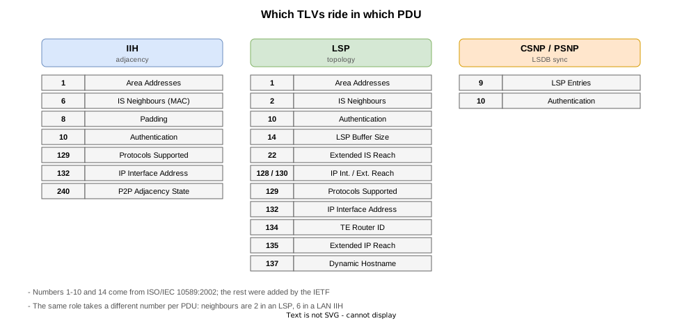
The same role takes a different CODE depending on the packet. Neighbouring routers are TLV 2 in an LSP (or 22 with wide metrics) but TLV 6 in a LAN IIH: the first carries System IDs, the second MAC addresses.
| TLV | Name | IIH | LSP | SNP | Source |
|---|---|---|---|---|---|
| 1 | Area Addresses | yes | yes | — | ISO/IEC 10589:2002 |
| 2 | IS Neighbours | — | yes | — | ISO/IEC 10589:2002 |
| 6 | IS Neighbours (MAC address) | yes | — | — | ISO/IEC 10589:2002 |
| 8 | Padding | yes | — | — | ISO/IEC 10589:2002 |
| 9 | LSP Entries | — | — | yes | ISO/IEC 10589:2002 |
| 10 | Authentication | yes | yes | yes | ISO/IEC 10589:2002 |
| 13 | Purge Originator Identification | — | yes | — | RFC 6232 |
| 14 | LSP Buffer Size | — | yes | — | ISO/IEC 10589:2002 |
| 22 | Extended IS Reachability | — | yes | — | RFC 5305 |
| 128 | IP Internal Reachability | — | yes | — | RFC 1195 |
| 129 | Protocols Supported | yes | yes | — | RFC 1195 |
| 130 | IP External Reachability | — | yes | — | RFC 1195 |
| 132 | IP Interface Address | yes | yes | — | RFC 1195 |
| 134 | TE Router ID | — | yes | — | RFC 5305 |
| 135 | Extended IP Reachability | — | yes | — | RFC 5305 |
| 137 | Dynamic Hostname | — | yes | — | RFC 5301 |
| 240 | P2P Adjacency State | yes | — | — | RFC 5303 |
The assignments live in IANA’s IS-IS TLV Codepoints registry.
The standard defines eleven TLVs
ISO/IEC 10589:2002 defines exactly eleven CODEs: 1 to 10 and 14.
| CODE | Name (as the standard writes it) | Carried in | Contents |
|---|---|---|---|
| 1 | Area Addresses | IIH / LSP | The set of area addresses of this IS |
| 2 | Intermediate System Neighbours | LSP | Neighbouring ISs and pseudonodes, with metrics |
| 3 | End System Neighbours | Level 1 LSP | Neighbouring end systems |
| 4 | Partition Designated Level 2 IS | Level 2 LSP | The designated router for the partition repair function |
| 5 | Prefix Neighbours | Level 2 LSP | Reachable address prefixes (CLNP) |
| 6 | Intermediate System Neighbours | LAN IIH | MAC addresses of neighbouring ISs (6 octets) |
| 7 | Intermediate System Neighbours | LAN IIH | The variable-length SNPA version |
| 8 | Padding | IIH | Filler that proves the MTU |
| 9 | LSP Entries | CSNP / PSNP | LSP ID, sequence number, lifetime and checksum |
| 10 | Authentication Information | Every PDU | Authentication data |
| 14 | originatingLSPBufferSize | LSP | The largest LSP this system generates |
Of these, 3, 4, 5 and 7 belong to the OSI era and never appear on a network that carries only IP: end-system adjacencies (3) are for when IS-IS handles end systems directly, and prefixes (5) are CLNP routes. In practice the ones you see are 1, 2, 6, 8, 9, 10 and 14.
What RFC 1195 added for IP
Carrying IP over IS-IS was defined by RFC 1195 (Integrated IS-IS), which uses CODEs from 128 upwards.
| TLV | Name | Contents |
|---|---|---|
| 128 | IP Internal Reachability | IP prefixes that belong to IS-IS itself, with metrics |
| 129 | Protocols Supported | The network-layer protocols carried. IPv4 is NLPID 0xCC |
| 130 | IP External Reachability | IP prefixes redistributed from another protocol |
| 132 | IP Interface Address | The router’s own interface addresses |
128 and 130 differ in where the route came from: IS-IS’s own routes go in 128, redistributed ones in 130. Both lay out four one-byte metrics of which only six bits hold the value (the narrow metric; see IS-IS metrics).
Bit 8 of the default metric in 128 and 130 was later redefined by RFC 5302 as the up/down bit, which marks routes leaked from Level 2 into Level 1 so that they cannot loop back.
Wide metrics and sub-TLVs in RFC 5305

RFC 5305 defines two new TLVs with wider metric fields.
| TLV | Name | Metric width | Replaces |
|---|---|---|---|
| 22 | Extended IS Reachability | 24 bits (3 bytes) | TLV 2 |
| 135 | Extended IP Reachability | 32 bits (4 bytes) | TLV 128 / 130 |
| 134 | TE Router ID | — | (new) the 4-byte router ID of the router originating the LSP |
What matters is that they carry sub-TLVs. TLV 22 is a System ID (7 bytes), a metric (3 bytes), a sub-TLV length (1 byte) and then 0 to 244 bytes of sub-TLVs, each of which is again a CODE / LENGTH / VALUE.
| Sub-TLV | Contents |
|---|---|
| 3 | Administrative group (colour, resource class) |
| 6 | IPv4 interface address |
| 8 | IPv4 neighbor address |
| 9 / 10 / 11 | Maximum / reservable / unreserved bandwidth |
| 18 | TE Default Metric |
TLV 135 has the same idea: a metric (4 bytes), a control byte (up/down bit, sub-TLV presence, prefix length), the prefix, and optional sub-TLVs.
Traffic engineering and segment routing both sit on top of this nesting. With a one-byte LENGTH, adding CODEs alone can never get past 255 bytes; sub-TLVs are what let a link or a prefix carry any number of attributes.
RFC 7794, for instance, defines Prefix Attribute Flags as sub-TLV 4 of TLV 135, carrying an N flag that says the prefix belongs to the advertising router itself. Segment routing uses it to decide what is a Node-SID.
Others worth knowing
| TLV | Name | Source | Role |
|---|---|---|---|
| 13 | Purge Originator Identification | RFC 6232 | The System ID of the router that purged an LSP (IS-IS LSPs and the link-state database) |
| 137 | Dynamic Hostname | RFC 5301 | A hostname for a System ID, which is what makes show output readable |
| 211 | Restart Signaling | RFC 5306 | Graceful restart |
| 240 | Point-to-Point Adjacency State | RFC 5303 | The point-to-point three-way handshake (IS-IS adjacencies and their states) |
| 242 | IS-IS Router CAPABILITY | RFC 7981 | Router-wide capabilities, such as the SRGB for segment routing |
| 232 / 236 | IPv6 Interface Address / IPv6 Reachability | RFC 5308 | IPv6 addresses and prefixes |
| 222 / 229 / 235 | MT-ISN / Multi-Topology / MT IP Reachability | RFC 5120 | Multi-topology |
The IPv6 and multi-topology TLVs are covered in IS-IS IPv6 Support and Multi-Topology.
Verification on real routers
Lab environment

Three routers, R1 to R2 to R3, with R1 to R2 point-to-point and R2 to R3 broadcast. The areas differ as well: R1 is Level 1, R2 is Level 1-2, R3 is Level 2 only.
One lab then shows the point-to-point TLVs (240 and 8), the broadcast ones (6, the pseudonode LSP and TLV 9 in CSNPs) and two different area addresses (1) side by side.
| Router | Level | NET | Lo0 | Links |
|---|---|---|---|---|
| R1 | level-1 | 49.0001.0010.0100.1001.00 | 1.1.1.1/32 | Gi0/0/0/0 10.1.2.1 (p2p) |
| R2 | level-1-2 | 49.0001.0020.0200.2002.00 | 2.2.2.2/32 | Gi0/0/0/0 10.1.2.2 (p2p, L1) / Gi0/0/0/1 10.2.3.2 (LAN, L2) |
| R3 | level-2-only | 49.0002.0030.0300.3003.00 | 3.3.3.3/32 | Gi0/0/0/0 10.2.3.3 (LAN) |
Verification STEPs
| STEP | Change | Purpose |
|---|---|---|
| 0 | Defaults (narrow, no redistribution) | The TLVs carried by each of IIH / LSP / CSNP / PSNP |
| 1 | Redistribute a static route into IS-IS on R3 | TLV 130 for external routes, against TLV 128 for internal ones |
| 2 | metric-style wide on all routers | The switch to TLV 22 / 135 and what their sub-TLVs hold |
| 3 | Put everything back (final state) | Same as STEP 0 |
The TLVs of each PDU (STEP 0)
Start with the point-to-point IIH, No.1 in the capture.
    ...1 0001 = PDU Type: P2P HELLO (17)
    Point-to-point Adjacency State (t=240, l=15)
    Protocols Supported (t=129, l=1)
    Restart Signaling (t=211, l=3)
    Area address(es) (t=1, l=4)
    IP Interface address(es) (t=132, l=4)
    Unknown code (t=21, l=4)
    Padding (t=8, l=255)
    Padding (t=8, l=255)
    Padding (t=8, l=255)
    Padding (t=8, l=255)
    Padding (t=8, l=255)
Padding (t=8, l=147)TLV 240 (P2P Adjacency State) and the run of TLV 8 (Padding) at the end are what make this a point-to-point IIH. Since one TLV stops at 255 bytes, the padding repeats the same CODE six times to reach the size that proves the MTU.
Unknown code (t=21, l=4) is a TLV tshark could not decode.
    Unknown code (t=21, l=4)
        Type: 21
        Length: 4
        Dissector for IS-IS CLV (21) code not implemented, Contact Wireshark developers if you want this supported
            [Expert Info (Note/Undecoded): Dissector for IS-IS CLV (21) code not implemented, Contact Wireshark developers if you want this supported]
                [Dissector for IS-IS CLV (21) code not implemented, Contact Wireshark developers if you want this supported]
                [Severity level: Note]
                [Group: Undecoded]
CODE 21 is the Flooding Parameters TLV from RFC 9681, “IS-IS Fast Flooding” (2024, Experimental), which exchanges parameters for faster flooding in IIHs and PSNPs. The adjacency came up normally even though the analyser did not know the TLV, exactly as the standard’s “unrecognised codes shall be ignored” requires.
Compare that with the broadcast side, No.2 in the LAN capture.
    ...1 0000 = PDU Type: L2 HELLO (16)
    Protocols Supported (t=129, l=1)
    Restart Signaling (t=211, l=3)
    Area address(es) (t=1, l=4)
    IP Interface address(es) (t=132, l=4)
    IS Neighbor(s) (t=6, l=6)
    Padding (t=8, l=255)
    Padding (t=8, l=255)
    Padding (t=8, l=255)
    Padding (t=8, l=255)
    Padding (t=8, l=255)
Padding (t=8, l=155)There is no TLV 240; TLV 6 (IS Neighbours) takes its place. The role is the same, but a point-to-point link carries the three-way state while a broadcast link carries the neighbour’s MAC address.
Next the LSP. Metrics are still narrow, so links are TLV 2 and prefixes TLV 128.
    ...1 0010 = PDU Type: L1 LSP (18)
    Area address(es) (t=1, l=4)
    Originating neighbor buffer size (t=14, l=2)
    Protocols supported (t=129, l=1)
    IP Interface address(es) (t=132, l=4)
    Hostname (t=137, l=2)
    IP Internal reachability (t=128, l=24)
IS Reachability (t=2, l=12) Area address(es) (t=1, l=4)
Type: 1
Length: 4
Area address (3): 49.0001
Originating neighbor buffer size (t=14, l=2)
Type: 14
Length: 2
Neighbor originating buffer size: 1492
Protocols supported (t=129, l=1)
Type: 129
Length: 1
NLPID: IP (0xcc)
NLPID: 0xcc
IP Interface address(es) (t=132, l=4)
Type: 132
Length: 4
IPv4 interface address: 1.1.1.1
Hostname (t=137, l=2)
Type: 137
Length: 2
Hostname: R1
IP Internal reachability (t=128, l=24)
Type: 128
Length: 24
IPv4 prefix: 1.1.1.1/32
..00 0000 = Default Metric: 0
.0.. .... = Default Metric IE: Internal
0... .... = Distribution: Up
..00 0000 = Delay Metric: 0
1... .... = Delay Metric: Not Supported
.0.. .... = Delay Metric: Internal
..00 0000 = Expense Metric: 0
1... .... = Expense Metric: Not Supported
.0.. .... = Expense Metric: Internal
..00 0000 = Error Metric: 0
1... .... = Error Metric: Not Supported
.0.. .... = Error Metric: Internal
IPv4 prefix: 10.1.2.0/24
..00 1010 = Default Metric: 10
.0.. .... = Default Metric IE: Internal
0... .... = Distribution: Up
..00 0000 = Delay Metric: 0
1... .... = Delay Metric: Not Supported
.0.. .... = Delay Metric: Internal
..00 0000 = Expense Metric: 0
1... .... = Expense Metric: Not Supported
.0.. .... = Expense Metric: Internal
..00 0000 = Error Metric: 0
1... .... = Error Metric: Not Supported
.0.. .... = Error Metric: InternalOne LSP carries the area address (1), the LSP buffer size (14), the protocols supported (129), the interface address (132), the hostname (137), the prefixes (128) and the neighbours (2).
CSNPs and PSNPs carry nothing but TLV 9.
    ...1 1001 = PDU Type: L2 CSNP (25)
    LSP entries (t=9, l=48)

    ...1 1010 = PDU Type: L1 PSNP (26)
    LSP entries (t=9, l=16)
The lengths differ because of how many LSPs they list (48 bytes is 3 entries, 16 bytes is 1; each entry is 16 bytes).
Redistribution brings out TLV 130 (STEP 1)
A static route for 192.168.30.0/24 is created on R3 and redistributed into IS-IS.
    IP External reachability (t=130, l=12)
        Type: 130
        Length: 12
        IPv4 prefix: 192.168.30.0/24
            ..00 0000 = Default Metric: 0
            .0.. .... = Default Metric IE: Internal
            0... .... = Distribution: Up
            ..00 0000 = Delay Metric: 0
            1... .... = Delay Metric: Not Supported
            .0.. .... = Delay Metric: Internal
            ..00 0000 = Expense Metric: 0
            1... .... = Expense Metric: Not Supported
            .0.. .... = Expense Metric: Internal
            ..00 0000 = Error Metric: 0
            1... .... = Error Metric: Not Supported
.0.. .... = Error Metric: InternalTLV 128 (its own prefixes) and TLV 130 (the redistributed one) now sit in the same LSP. The field layout is identical; only the CODE differs.
RP/0/RP0/CPU0:R3#show isis database
Thu Sep 10 04:33:18.603 UTC

IS-IS 1 (Level-2) Link State Database
LSPID                 LSP Seq Num  LSP Checksum  LSP Holdtime/Rcvd  ATT/P/OL
R2.00-00              0x0000000a   0xadd6        828  /1200         0/0/0
R3.00-00            * 0x00000007   0x45be        913  /*            0/0/0
R3.01-00              0x00000004   0xd0f9        1056 /*            0/0/0

 Total Level-2 LSP count: 3     Local Level-2 LSP count: 1
Wide metrics swap in TLV 22 and 135 (STEP 2)
All three routers are set to metric-style wide.
    Extended IP Reachability (t=135, l=37)
        Type: 135
        Length: 37
        Ext. IP Reachability: 3.3.3.3/32
            Metric: 0
            0... .... = Distribution: Up
            .1.. .... = Sub-TLV: Yes
            ..10 0000 = Prefix Length: 32
            IPv4 prefix: 3.3.3.3
            SubCLV Length: 3
            subTLV: Prefix Attribute Flags (c=4, l=1): Flags:--N
                Code: Prefix Attribute Flags (4)
                Length: 1
                Flags: 0x20, Node
                    0... .... = External Prefix: Not set
                    .0.. .... = Re-advertisement: Not set
..1. .... = Node: SetTLV 2 has become 22, and TLVs 128 and 130 have merged into 135. Every prefix now carries sub-TLV 4 (Prefix Attribute Flags), and the loopback 3.3.3.3/32 has the N flag set, marking it as the advertising router’s own prefix.
The redistributed route carries the X flag of that same sub-TLV.
        Ext. IP Reachability: 192.168.30.0/24
            Metric: 0
            0... .... = Distribution: Up
            .1.. .... = Sub-TLV: Yes
            ..01 1000 = Prefix Length: 24
            IPv4 prefix: 192.168.30.0
            SubCLV Length: 3
            subTLV: Prefix Attribute Flags (c=4, l=1): Flags:X--
                Code: Prefix Attribute Flags (4)
                Length: 1
                Flags: 0x80, External Prefix
                    1... .... = External Prefix: Set
                    .0.. .... = Re-advertisement: Not set
                    ..0. .... = Node: Not set
Wide has no TLV 130. Whether a prefix is internal or external is carried by the X flag in a sub-TLV of TLV 135: what was a separate CODE under narrow became a sub-TLV of the same CODE under wide.
show isis database verbose expands the sub-TLVs.
R3.00-00              0x00000008   0xcdd8        971  /1200         0/0/0
  Area Address:   49.0002
  LSP MTU:        1492
  NLPID:          0xcc
  IP Address:     3.3.3.3
  Hostname:       R3
  Metric: 10         IS-Extended R3.01
  Metric: 0          IP-Extended 3.3.3.3/32
    Prefix Attribute Flags: X:0 R:0 N:1 E:0 A:0
  Metric: 10         IP-Extended 10.2.3.0/24
    Prefix Attribute Flags: X:0 R:0 N:0 E:0 A:0
  Metric: 0          IP-Extended 192.168.30.0/24
    Prefix Attribute Flags: X:1 R:0 N:0 E:0 A:0
R3.01-00              0x00000005   0xf8c0        971  /1200         0/0/0
  Metric: 0          IS-Extended R2.00
  Metric: 0          IS-Extended R3.00
Putting it back (STEP 3)
Removing metric-style, the redistribution and the static route returns everything to the initial state (the ..._run.txt files of STEP 0 and STEP 3 match).
RP/0/RP0/CPU0:R2#show isis database
Thu Sep 10 04:41:36.389 UTC

IS-IS 1 (Level-1) Link State Database
LSPID                 LSP Seq Num  LSP Checksum  LSP Holdtime/Rcvd  ATT/P/OL
R1.00-00              0x00000008   0x27f1        1040 /1200         0/0/0
R2.00-00            * 0x0000000e   0x926d        1050 /*            1/0/0

 Total Level-1 LSP count: 2     Local Level-1 LSP count: 1

IS-IS 1 (Level-2) Link State Database
LSPID                 LSP Seq Num  LSP Checksum  LSP Holdtime/Rcvd  ATT/P/OL
R2.00-00            * 0x00000010   0xa1dc        1050 /*            0/0/0
R3.00-00              0x00000009   0xdbbd        1020 /1200         0/0/0
R3.01-00              0x00000006   0xccfb        1020 /1200         0/0/0

 Total Level-2 LSP count: 3     Local Level-2 LSP count: 1
Verification configs and show output
For every STEP the following kinds of output were captured from all three routers. The verification config is these ..._run.txt files (the final state is STEP 3).
| File | Contents |
|---|---|
..._show.txt | show version / show interface description / show route / show route isis / show isis / show isis hostname / show isis interface / show isis interface brief / show isis neighbors / show isis neighbors detail / show isis database / show isis database detail / show isis database verbose / show isis topology / show isis adjacency / show isis adjacency-log / show isis spf-log / show isis lsp-log / show isis statistics / show cef |
..._log.txt | show logging narrowed to the range of that STEP (STEP 0 holds the whole history since boot) |
..._run.txt | show running-config at that STEP (that is, the verification config for the STEP) |
STEP 0: defaults (narrow, no redistribution)
| Router | show output | syslog | running-config |
|---|---|---|---|
| R1 | show | log | run |
| R2 | show | log | run |
| R3 | show | log | run |
STEP 1: redistribute a static route on R3
| Router | show output | syslog | running-config |
|---|---|---|---|
| R1 | show | log | run |
| R2 | show | log | run |
| R3 | show | log | run |
STEP 2: metric-style wide on all routers
| Router | show output | syslog | running-config |
|---|---|---|---|
| R1 | show | log | run |
| R2 | show | log | run |
| R3 | show | log | run |
STEP 3: put everything back (final state)
| Router | show output | syslog | running-config |
|---|---|---|---|
| R1 | show | log | run |
| R2 | show | log | run |
| R3 | show | log | run |
There are two capture files per STEP: the point-to-point side (R1 to R2) and the broadcast side (R2 to R3).
Download the STEP 0 p2p capture (isis-tlv-step0-p2p.pcap)
Download the STEP 0 LAN capture (isis-tlv-step0-lan.pcap)
Download the STEP 1 p2p capture (isis-tlv-step1-p2p.pcap)
Download the STEP 1 LAN capture (isis-tlv-step1-lan.pcap)
Download the STEP 2 p2p capture (isis-tlv-step2-p2p.pcap)
Download the STEP 2 LAN capture (isis-tlv-step2-lan.pcap)
References
| Standard | Title | Summary |
|---|---|---|
| ISO/IEC 10589:2002 (2nd edition) | Intermediate System to Intermediate System intra-domain routeing information exchange protocol | The IS-IS specification itself. This article draws on 9.5 to 9.13, which define the shape of a TLV and the CODEs of each PDU (the handling of unknown CODEs is in 9.5 to 9.7 and 9.8). |
| IANA IS-IS TLV Codepoints | IS-IS TLV Codepoints | The registry of CODE assignments and which PDUs (IIH / LSP / SNP) may carry each one. |
| RFC 1195 | Use of OSI IS-IS for Routing in TCP/IP and Dual Environments | Defines TLVs 128, 129, 130 and 132, which carry IP. |
| RFC 5301 | Dynamic Hostname Exchange Mechanism for IS-IS | Defines the hostname TLV 137. |
| RFC 5302 | Domain-Wide Prefix Distribution with Two-Level IS-IS | Redefined bit 8 of the default metric in TLVs 128 and 130 as the up/down bit. |
| RFC 5303 | Three-Way Handshake for IS-IS Point-to-Point Adjacencies | Defines TLV 240, carried in point-to-point IIHs. |
| RFC 5305 | IS-IS Extensions for Traffic Engineering | Defines TLV 22 (24 bits), TLV 135 (32 bits), TLV 134, and the sub-TLVs of TLV 22. |
| RFC 6232 | Purge Originator Identification TLV for IS-IS | Defines TLV 13, which names the purging router. |
| RFC 7794 | IS-IS Prefix Attributes for Extended IPv4 and IPv6 Reachability | Defines sub-TLV 4 (Prefix Attribute Flags) of TLV 135 and others. |
| RFC 7981 | IS-IS Extensions for Advertising Router Information | Defines TLV 242, which carries router-wide capabilities. |
Related articles
- What is IS-IS
- IS-IS NSAP Addresses and the NET (System ID)
- IS-IS Multiple Area Addresses (Multihoming), Merging and Splitting Areas
- IS-IS Level 1 and Level 2 (the hierarchy)
- IS-IS Packet Types and Header Format
- IS-IS Adjacency Formation and States
- IS-IS DIS and the Pseudonode
- IS-IS Network Types (broadcast / point-to-point)
- IS-IS Metrics (narrow and wide)
- IS-IS Authentication (hello-password and lsp-password)
- IS-IS LSPs and the Link-State Database
- The Main IS-IS TLVs
- IS-IS Flooding and LSDB Synchronisation
- IS-IS SPF Computation and Route Selection
- IS-IS ECMP (Equal-Cost Multipath)
- The IS-IS ATT Bit and the Level 1 Default Route
- IS-IS Route Leaking and the Up/Down Bit
- IS-IS Route Summarization
- The IS-IS Overload Bit
- IS-IS IPv6 Support and Multi-Topology (TLV 236 / MT ID 2)
- IS-IS Hello and Holding Time
- IS-IS Convergence Timers (SPF / LSP Generation)
- IS-IS Flooding Timers (LSP Interval, Retransmission, CSNP / PSNP)
- IS-IS Link Failure and Path Switchover
- IS-IS Redistribution (connected / static)
- IS-IS Redistribution of BGP Routes