What a network-LSA is
A network-LSA (type 2) is the LSA that stands for a broadcast segment itself. Where a router-LSA (type 1) describes one router’s own doorstep, this one describes who is sitting on one piece of Ethernet. Only the DR of that segment originates it.
| Item | Content |
|---|---|
| Who originates it | Only the DR. Neither the BDR nor a DROTHER does |
| How many | One per segment. A DR on two segments originates two |
| How far it travels | Only inside that area |
| Link State ID | The DR’s interface address, not its router ID |
| Advertising Router | The DR’s router ID |
That the link state ID and the advertising router are two different values of the same router is characteristic of this LSA.
Why a segment becomes a single vertex
A point-to-point link needs nothing more than the two router-LSAs pointing at each other: it is a line between two points. A broadcast segment, though, is a surface any number of routers can sit on, and describing it as a collection of lines explodes.

Four routers make 6 edges (12 counting both directions); ten routers make 45. It grows with the square of the count. So OSPF makes the segment itself one vertex of the graph and draws a single edge from each router to it. The number of edges is then just the number of routers.
That vertex is exactly what a network-LSA is. Without type 2, the SPF calculation could not handle a broadcast segment at all.
Packet format
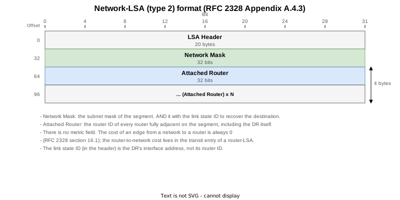
After the 20-byte common header there is nothing but a four-byte network mask and a list of four-byte attached routers.
| Field | Size | Content |
|---|---|---|
| Network Mask | 4 bytes | the subnet mask of the segment |
| Attached Router | 4 bytes x N | the router ID of every router fully adjacent on the segment, the DR itself included |
There is no metric field. The cost of an edge from a network to a router is fixed at 0 (RFC 2328 section 16.1). The cost in the other direction, from a router to the network, lives in the transit entry of that router’s router-LSA.
Note also that the destination prefix is written nowhere. It is recovered by ANDing the link state ID (the DR’s address) with the network mask: 10.0.0.1 and /24 give 10.0.0.0/24.
Lab topology

| Router | Lo0 | Gi0/0/0/0 | Priority | Role at boot |
|---|---|---|---|---|
| R1 | 1.1.1.1/32 | 10.0.0.1/24 | 100 | DR |
| R2 | 2.2.2.2/32 | 10.0.0.2/24 | 50 | BDR |
| R3 | 3.3.3.3/32 | 10.0.0.3/24 | 0 | DROTHER |
| R4 | 4.4.4.4/32 | 10.0.0.4/24 | default (1) | DROTHER |
All four are in a single area (area 0) and Lo0 is passive enable. Only R3 has priority 0, so it can never be DR or BDR. It is still on the segment, so it should still appear as an attached router.
DR and BDR election itself is covered in DR and BDR. This article is about how the outcome of that election shows up in the network-LSA.
| STEP | Change | What it confirms |
|---|---|---|
| 0 | Right after boot | The Network-LSA from the DR R1: the link state ID is the DR’s interface address, four attached routers |
| 1 | R3 (priority 0) shut down | The DR is unchanged and the attached routers drop to three |
| 2 | R3 restored | Back to four |
| 3 | The DR R1 shut down | The new DR R2 originates a new Network-LSA (a different link state ID); what happens to R1’s old one |
| 4 | R1 restored | R1 comes back as a DROTHER |
| 5 | R1, R3 and R4 shut down | A DR with no full adjacency originates no Network-LSA |
| 6 | Everything restored | Final state |
The segment and the LSA side by side

Here is the network-LSA right after boot. show ospf database network self-originate prints only what this router originated as DR, so only R1 has anything to show.
RP/0/RP0/CPU0:R1#show ospf database network self-originate
Tue Sep  8 10:11:32.960 UTC


            OSPF Router with ID (1.1.1.1) (Process ID 1)

		Net Link States (Area 0)

  Routing Bit Set on this LSA
  LS age: 68
  Options: (No TOS-capability, DC)
  LS Type: Network Links
  Link State ID: 10.0.0.1 (address of Designated Router)
  Advertising Router: 1.1.1.1
  LS Seq Number: 80000002
  Checksum: 0x9960
  Length: 40
  Network Mask: /24
	Attached Router: 1.1.1.1
	Attached Router: 2.2.2.2
	Attached Router: 3.3.3.3
Attached Router: 4.4.4.4| Field | Value | Where it comes from |
|---|---|---|
| Link State ID | 10.0.0.1 | the interface address of R1, the DR — not its router ID 1.1.1.1 |
| Advertising Router | 1.1.1.1 | R1’s router ID |
| Network Mask | /24 | the mask of the segment; the destination 10.0.0.0/24 is the AND of the two |
| Attached Router | 1.1.1.1 / 2.2.2.2 / 3.3.3.3 / 4.4.4.4 | all four, including R3 with priority 0 and R1 the DR itself |
R3 appearing there despite its priority of 0 is the point. Being unable to become DR and being on the segment are separate things, and the attached router list records only the second.
All four router-LSAs point at the same value
If the network-LSA is a vertex, where are the edges leading to it? In the transit entry of each router’s router-LSA. All four write the DR’s address as the Link ID.
| Router | Link ID of the transit entry | Link Data |
|---|---|---|
| R1 | 10.0.0.1 | 10.0.0.1 |
| R2 | 10.0.0.1 | 10.0.0.2 |
| R3 | 10.0.0.1 | 10.0.0.3 |
| R4 | 10.0.0.1 | 10.0.0.4 |
The Link ID is 10.0.0.1 on all four and only the Link Data differs. That shared Link ID is the key that joins router-LSAs to the network-LSA: SPF looks for the network-LSA whose link state ID matches the Link ID of a transit entry and draws the edge there.
Listing the LSDB one line at a time shows the shape directly.
RP/0/RP0/CPU0:R2#show ospf database
Tue Sep  8 10:11:51.818 UTC


            OSPF Router with ID (2.2.2.2) (Process ID 1)

		Router Link States (Area 0)

Link ID         ADV Router      Age         Seq#       Checksum Link count
1.1.1.1         1.1.1.1         95          0x80000003 0x0015e8 2
2.2.2.2         2.2.2.2         94          0x80000003 0x0005eb 2
3.3.3.3         3.3.3.3         88          0x80000003 0x00f4ee 2
4.4.4.4         4.4.4.4         88          0x80000003 0x00e4f1 2

		Net Link States (Area 0)

Link ID         ADV Router      Age         Seq#       Checksum
10.0.0.1        1.1.1.1         88          0x80000002 0x009960
Four routers give four router-LSAs, and one broadcast segment gives one network-LSA. If those numbers do not add up, either an adjacency is not forming or a network type is set differently from what you assumed.
On the wire, the position of the network mask and the list of attached routers are visible directly. This is packet No.142.
Open Shortest Path First
    OSPF Header
        Version: 2
        Message Type: LS Update (4)
        Packet Length: 68
        Source OSPF Router: 1.1.1.1
        Area ID: 0.0.0.0 (Backbone)
        Checksum: 0xa50a [correct]
        Instance ID: Base IPv4 Unicast Instance (0)
        Auth Type: Null (0)
        Auth Data (none): 0000000000000000
    LS Update Packet
        Number of LSAs: 1
        LSA-type 2 (Network-LSA), len 40
            .000 0000 0000 0001 = LS Age (seconds): 1
            0... .... .... .... = Do Not Age Flag: 0
            Options: 0x22, (DC) Demand Circuits, (E) External Routing
                0... .... = DN: Not set
                .0.. .... = (O) Opaque: Not set
                ..1. .... = (DC) Demand Circuits: Supported
                ...0 .... = (L) LLS Data block: Not Present
                .... 0... = (N) NSSA: Not supported
                .... .0.. = (MC) Multicast: Not capable
                .... ..1. = (E) External Routing: Capable
                .... ...0 = (MT) Multi-Topology Routing: No
            LS Type: Network-LSA (2)
            Link State ID: 10.0.0.1
            Advertising Router: 1.1.1.1
            Sequence Number: 0x80000004
            Checksum: 0x9562
            Length: 40
            Netmask: 255.255.255.0
            Attached Router: 1.1.1.1
            Attached Router: 2.2.2.2
            Attached Router: 3.3.3.3
Attached Router: 4.4.4.4What changes when the segment changes
The four-router segment was taken apart one router at a time to see how the network-LSA follows. Across the seven STEPs:
| STEP | Change | Originator | Link State ID | Seq | Attached routers |
|---|---|---|---|---|---|
| 0 | right after boot | R1 | 10.0.0.1 | 80000002 | 4 |
| 1 | shutdown on R3 (priority 0) | R1 | 10.0.0.1 | 80000003 | 3 (R3 drops out) |
| 2 | R3 restored | R1 | 10.0.0.1 | 80000004 | 4 |
| 3 | shutdown on R1, the DR | R2 | 10.0.0.2 | 80000001 | 3 |
| 4 | R1 restored | R2 | 10.0.0.2 | 80000002 | 4 (R1 returns) |
| 5 | shutdown on R1, R3 and R4 | — | the network-LSA is gone | — | — |
| 6 | everything restored (final state) | R2 | 10.0.0.2 | 80000005 | 4 |
Over the same period, R2’s router-LSA represented the segment like this.
| STEP | The segment in R2’s router-LSA |
|---|---|
| 0-2 | transit to 10.0.0.1 |
| 3-4 | transit to 10.0.0.2 (following the change of DR) |
| 5 | stub 10.0.0.0 |
| 6 | transit to 10.0.0.2 |
One DROTHER leaves: only the attached router list shrinks
Shutting down R3, the priority 0 router, removes 3.3.3.3 from the attached routers.
RP/0/RP0/CPU0:R1#show ospf database network self-originate
Tue Sep  8 10:14:43.582 UTC


            OSPF Router with ID (1.1.1.1) (Process ID 1)

		Net Link States (Area 0)

  Routing Bit Set on this LSA
  LS age: 56
  Options: (No TOS-capability, DC)
  LS Type: Network Links
  Link State ID: 10.0.0.1 (address of Designated Router)
  Advertising Router: 1.1.1.1
  LS Seq Number: 80000003
  Checksum: 0x8880
  Length: 36
  Network Mask: /24
	Attached Router: 1.1.1.1
	Attached Router: 2.2.2.2
	Attached Router: 4.4.4.4
Neither the link state ID nor the advertising router changes. The DR did not change, so the identity of the LSA is the same and only its list is updated. The sequence number went from 80000002 to 80000003.
The DR goes down: a different link state ID takes over
This is the heart of it. With R1 gone, R2 — the BDR — is promoted to DR, and R2 originates a brand-new network-LSA whose link state ID is its own address.
RP/0/RP0/CPU0:R2#show ospf database network self-originate
Tue Sep  8 10:22:28.507 UTC


            OSPF Router with ID (2.2.2.2) (Process ID 1)

		Net Link States (Area 0)

  Routing Bit Set on this LSA
  LS age: 142
  Options: (No TOS-capability, DC)
  LS Type: Network Links
  Link State ID: 10.0.0.2 (address of Designated Router)
  Advertising Router: 2.2.2.2
  LS Seq Number: 80000001
  Checksum: 0xb845
  Length: 36
  Network Mask: /24
	Attached Router: 2.2.2.2
	Attached Router: 3.3.3.3
	Attached Router: 4.4.4.4
The link state ID moved from 10.0.0.1 to 10.0.0.2 and the sequence number starts again at 80000001. The same segment, but a completely different LSA. An LSA is identified by the triple of LS type, link state ID and advertising router, so a change of DR changes two of the three.
The packet confirms it.
Open Shortest Path First
    OSPF Header
        Version: 2
        Message Type: LS Update (4)
        Packet Length: 64
        Source OSPF Router: 2.2.2.2
        Area ID: 0.0.0.0 (Backbone)
        Checksum: 0x802f [correct]
        Instance ID: Base IPv4 Unicast Instance (0)
        Auth Type: Null (0)
        Auth Data (none): 0000000000000000
    LS Update Packet
        Number of LSAs: 1
        LSA-type 2 (Network-LSA), len 36
            .000 0000 0000 0001 = LS Age (seconds): 1
            0... .... .... .... = Do Not Age Flag: 0
            Options: 0x22, (DC) Demand Circuits, (E) External Routing
                0... .... = DN: Not set
                .0.. .... = (O) Opaque: Not set
                ..1. .... = (DC) Demand Circuits: Supported
                ...0 .... = (L) LLS Data block: Not Present
                .... 0... = (N) NSSA: Not supported
                .... .0.. = (MC) Multicast: Not capable
                .... ..1. = (E) External Routing: Capable
                .... ...0 = (MT) Multi-Topology Routing: No
            LS Type: Network-LSA (2)
            Link State ID: 10.0.0.2
            Advertising Router: 2.2.2.2
            Sequence Number: 0x80000001
            Checksum: 0xb845
            Length: 36
            Netmask: 255.255.255.0
            Attached Router: 2.2.2.2
            Attached Router: 3.3.3.3
Attached Router: 4.4.4.4The old network-LSA does not go away at once
So what happened to the 10.0.0.1 LSA that R1 had been originating? It stayed in the LSDB, un-withdrawn.
RP/0/RP0/CPU0:R2#show ospf database network
Tue Sep  8 10:22:27.255 UTC


            OSPF Router with ID (2.2.2.2) (Process ID 1)

		Net Link States (Area 0)

  LS age: 360
  Options: (No TOS-capability, DC)
  LS Type: Network Links
  Link State ID: 10.0.0.1 (address of Designated Router)
  Advertising Router: 1.1.1.1
  LS Seq Number: 80000004
  Checksum: 0x9562
  Length: 40
  Network Mask: /24
	Attached Router: 1.1.1.1
	Attached Router: 2.2.2.2
	Attached Router: 3.3.3.3
	Attached Router: 4.4.4.4

  Routing Bit Set on this LSA
  LS age: 140
  Options: (No TOS-capability, DC)
  LS Type: Network Links
  Link State ID: 10.0.0.2 (address of Designated Router)
  Advertising Router: 2.2.2.2
  LS Seq Number: 80000001
  Checksum: 0xb845
  Length: 36
  Network Mask: /24
	Attached Router: 2.2.2.2
	Attached Router: 3.3.3.3
	Attached Router: 4.4.4.4
Both 10.0.0.1 (advertising router 1.1.1.1) and 10.0.0.2 (advertising router 2.2.2.2) are listed, and the LS age of the first keeps climbing.
R1 itself, on the other hand, has already dropped it from its own LSDB.
RP/0/RP0/CPU0:R1#show ospf database network
Tue Sep  8 10:22:04.305 UTC


            OSPF Router with ID (1.1.1.1) (Process ID 1)
The output ends at the heading. R1 decided it was no longer the DR and withdrew the LSA, but with its interface down it has no way to tell the segment.
This does no harm, because SPF never uses that LSA. The transit entries of R2, R3 and R4 already point at 10.0.0.2, so the 10.0.0.1 network-LSA is an orphaned vertex that no router-LSA refers to. The two-way check of RFC 2328 section 16.1 discards it and the route calculation is unaffected. It simply ages up to MaxAge (3600 seconds) and disappears.
In other words, withdrawing an LSA only works if there is still a path to carry the withdrawal. That is why the LSAs of a router isolated by a failure linger visibly for a while.
The withdrawal flies the moment the router comes back
Bringing R1’s interface back up re-establishes the adjacency, and R1 immediately withdraws the old LSA by setting it to MaxAge. Packet No.334 is that moment.
Open Shortest Path First
    OSPF Header
        Version: 2
        Message Type: LS Update (4)
        Packet Length: 68
        Source OSPF Router: 1.1.1.1
        Area ID: 0.0.0.0 (Backbone)
        Checksum: 0x98f9 [correct]
        Instance ID: Base IPv4 Unicast Instance (0)
        Auth Type: Null (0)
        Auth Data (none): 0000000000000000
    LS Update Packet
        Number of LSAs: 1
        LSA-type 2 (Network-LSA), len 40
            .000 1110 0001 0000 = LS Age (seconds): 3600
            0... .... .... .... = Do Not Age Flag: 0
            Options: 0x22, (DC) Demand Circuits, (E) External Routing
                0... .... = DN: Not set
                .0.. .... = (O) Opaque: Not set
                ..1. .... = (DC) Demand Circuits: Supported
                ...0 .... = (L) LLS Data block: Not Present
                .... 0... = (N) NSSA: Not supported
                .... .0.. = (MC) Multicast: Not capable
                .... ..1. = (E) External Routing: Capable
                .... ...0 = (MT) Multi-Topology Routing: No
            LS Type: Network-LSA (2)
            Link State ID: 10.0.0.1
            Advertising Router: 1.1.1.1
            Sequence Number: 0x80000005
            Checksum: 0x9363
            Length: 40
            Netmask: 255.255.255.0
            Attached Router: 1.1.1.1
            Attached Router: 2.2.2.2
            Attached Router: 3.3.3.3
Attached Router: 4.4.4.4LS Age (seconds): 3600 is set. This is premature aging, the procedure a router uses to withdraw an LSA it originated: re-flood it with MaxAge (RFC 2328 section 14.1). The sequence number is also advanced to 80000005, so receivers treat it as the newest version and, being expired, remove it from the LSDB.
The source of the LS Update matters too: 1.1.1.1. Only the router that created an LSA can withdraw it.
After the recovery, R2’s network-LSA keeps the link state ID 10.0.0.2 and gets 1.1.1.1 back in its attached router list.
RP/0/RP0/CPU0:R2#show ospf database network self-originate
Tue Sep  8 10:26:08.989 UTC


            OSPF Router with ID (2.2.2.2) (Process ID 1)

		Net Link States (Area 0)

  Routing Bit Set on this LSA
  LS age: 136
  Options: (No TOS-capability, DC)
  LS Type: Network Links
  Link State ID: 10.0.0.2 (address of Designated Router)
  Advertising Router: 2.2.2.2
  LS Seq Number: 80000002
  Checksum: 0x7183
  Length: 40
  Network Mask: /24
	Attached Router: 1.1.1.1
	Attached Router: 2.2.2.2
	Attached Router: 3.3.3.3
	Attached Router: 4.4.4.4
The link state ID does not revert to 10.0.0.1. DR election is non-preemptive, so R2 stays DR even though R1 with its priority of 100 is back. R1 returns as a DROTHER and simply rejoins the attached router list.
One router left on the segment: the network-LSA disappears
Finally, everything but R2, the DR, is shut down.
RP/0/RP0/CPU0:R2#show ospf database network
Tue Sep  8 10:30:00.923 UTC


            OSPF Router with ID (2.2.2.2) (Process ID 1)
The network-LSA is gone entirely. show ospf interface brief still calls R2 the DR, but a DR with no full adjacency originates no network-LSA (RFC 2328 section 12.4.2). A broadcast segment with one router on it is not worth treating as a surface.
At the same time, the segment turns from a transit into a stub in R2’s router-LSA.
RP/0/RP0/CPU0:R2#show ospf database router self-originate
Tue Sep  8 10:30:03.461 UTC


            OSPF Router with ID (2.2.2.2) (Process ID 1)

		Router Link States (Area 0)

  LS age: 96
  Options: (No TOS-capability, DC)
  LS Type: Router Links
  Link State ID: 2.2.2.2
  Advertising Router: 2.2.2.2
  LS Seq Number: 80000005
  Checksum: 0xea10
  Length: 48
   Number of Links: 2

    Link connected to: a Stub Network
     (Link ID) Network/subnet number: 2.2.2.2
     (Link Data) Network Mask: 255.255.255.255
      Number of TOS metrics: 0
       TOS 0 Metrics: 1

    Link connected to: a Stub Network
     (Link ID) Network/subnet number: 10.0.0.0
     (Link Data) Network Mask: 255.255.255.0
      Number of TOS metrics: 0
       TOS 0 Metrics: 1
A stub entry for 10.0.0.0 / 255.255.255.0. With the network-LSA vertex gone, the router-LSA advertises the prefix directly instead. The same physical segment is represented differently in the graph depending on how many routers sit on it.
How SPF treats it
A network-LSA is a vertex, and it carries no cost. Here are the costs as R2 computes them.
RP/0/RP0/CPU0:R2#show ospf routes
Tue Sep  8 10:11:55.997 UTC

Topology Table for ospf 1 with ID 2.2.2.2

Codes: O - Intra area, O IA - Inter area
       O E1 - External type 1, O E2 - External type 2
       O N1 - NSSA external type 1, O N2 - NSSA external type 2

O    1.1.1.1/32, metric 2
       10.0.0.1, from 1.1.1.1, via GigabitEthernet0/0/0/0, ifIndex 3, path-id 1
O    2.2.2.2/32, metric 1
       2.2.2.2, directly connected, via Loopback0, ifIndex 7
O    3.3.3.3/32, metric 2
       10.0.0.3, from 3.3.3.3, via GigabitEthernet0/0/0/0, ifIndex 3, path-id 1
O    4.4.4.4/32, metric 2
       10.0.0.4, from 4.4.4.4, via GigabitEthernet0/0/0/0, ifIndex 3, path-id 1
O    10.0.0.0/24, metric 1
10.0.0.2, directly connected, via GigabitEthernet0/0/0/0, ifIndex 3| Destination | How the cost adds up | show ospf routes |
|---|---|---|
10.0.0.0/24 | R2 to the segment, 1 | metric 1 |
1.1.1.1/32 | R2 to the segment 1 + the segment to R1 0 + R1’s stub 1 | metric 2 |
3.3.3.3/32 | the same, with R3’s stub | metric 2 |
4.4.4.4/32 | the same, with R4’s stub | metric 2 |
Crossing the segment costs only the 1 charged on the way in. The edge leading back out of a network to a router is free, so every one of the four peers comes out at metric 2. That matches what a broadcast segment actually is: one hop reaches everybody.
Had there been no type 2 and the segment been modelled as a full mesh, the same result would have required cost information for six edges in both directions. The network-LSA makes the representation compact and the arithmetic simple at the same time.
Summary
| What you want to know | Where to look |
|---|---|
| Which router is the DR of a segment | the advertising router of the network-LSA (a router ID) |
| The DR’s interface address | the link state ID |
| Who is on the segment | the attached router list; priority 0 routers are included |
| The prefix of the segment | the link state ID ANDed with the network mask |
| Whether the DR has changed | a changed link state ID means it has |
| Whether a segment is down to one router | the network-LSA is gone and the router-LSA shows a stub |
A network-LSA is a short LSA, but the two things you most want to know in operations — who the DR is and who is on the segment — are both in it. Reading the DR’s one network-LSA is often faster than running show ospf neighbor on every router.
References
| Document | Section | Content |
|---|---|---|
| RFC 2328 | Section 12.4.2 | originating network-LSAs: the DR originates it, and not at all without a full adjacency |
| RFC 2328 | Section 13.4 | withdrawing an LSA you originated by setting MaxAge (premature aging) |
| RFC 2328 | Section 14.1 | premature aging: only the originating router may withdraw an LSA |
| RFC 2328 | Appendix A.4.3 | the packet format of a network-LSA (there is no metric field) |
| RFC 2328 | Section 16.1 | the SPF calculation, the network vertex, the zero-cost edge back to a router, and the two-way check |
| RFC 2328 | Section 9.4 | that DR election is non-preemptive |
Lab setup
Four XRd routers (IOS XR 26.1.1) in CML on one Ethernet segment (10.0.0.0/24). The only change made at any STEP was shutdown on an interface; the OSPF configuration was never touched after boot. The capture was taken at one point, between R2 and the switch, covering all 24 minutes — R2 never goes down, so the change of DR and the withdrawal both land in this single file.
Verification config and show output
Three kinds of file were collected from all four routers at every STEP, split per router. The verification config is the ..._run.txt file (the final state is the one from STEP 6).
| File | Content |
|---|---|
..._show.txt | show version / show interface description / show route / show route ospf / show ospf / show ospf interface / show ospf interface brief / show ospf neighbor / show ospf neighbor detail / show ospf database / show ospf database router / show ospf database network / show ospf statistics interface / show ospf database network self-originate / show ospf database router self-originate / show ospf border-routers / show ospf routes / show ospf database database-summary |
..._log.txt | show logging narrowed to the range of that STEP |
..._run.txt | show running-config at that STEP (the verification config) |
Adding show ospf database network self-originate is what made this article work: it prints only the network-LSA this router originated as DR, so seeing which router has output at all identifies the DR.
STEP 0: right after boot (R1 is DR)
| Router | show output | syslog | running-config |
|---|---|---|---|
| R1 | show | log | run |
| R2 | show | log | run |
| R3 | show | log | run |
| R4 | show | log | run |
STEP 1: shutdown on R3 (priority 0)
| Router | show output | syslog | running-config |
|---|---|---|---|
| R1 | show | log | run |
| R2 | show | log | run |
| R3 | show | log | run |
| R4 | show | log | run |
STEP 2: R3 restored
| Router | show output | syslog | running-config |
|---|---|---|---|
| R1 | show | log | run |
| R2 | show | log | run |
| R3 | show | log | run |
| R4 | show | log | run |
STEP 3: shutdown on R1, the DR (R2 is promoted)
| Router | show output | syslog | running-config |
|---|---|---|---|
| R1 | show | log | run |
| R2 | show | log | run |
| R3 | show | log | run |
| R4 | show | log | run |
STEP 4: R1 restored (R2 stays DR)
| Router | show output | syslog | running-config |
|---|---|---|---|
| R1 | show | log | run |
| R2 | show | log | run |
| R3 | show | log | run |
| R4 | show | log | run |
STEP 5: shutdown on R1, R3 and R4 (only R2, the DR, is left)
| Router | show output | syslog | running-config |
|---|---|---|---|
| R1 | show | log | run |
| R2 | show | log | run |
| R3 | show | log | run |
| R4 | show | log | run |
STEP 6: everything restored (final state)
| Router | show output | syslog | running-config |
|---|---|---|---|
| R1 | show | log | run |
| R2 | show | log | run |
| R3 | show | log | run |
| R4 | show | log | run |
Related articles
- What is OSPF
- OSPF Router ID
- OSPF Behavior When Router IDs Collide
- OSPF Packet Types and Header Format
- OSPF Authentication
- OSPF Neighbor States
- OSPF Options Field
- OSPF DR and BDR
- OSPF Network Types
- OSPF Cost (Metric)
- OSPF Equal-Cost Multi-Path (ECMP)
- OSPF External Routes (Redistributing Static Routes)
- OSPF RFC1583 Compatibility (External Route Selection Rules)
- OSPF Forwarding Address of AS External Routes
- OSPF Multiple Areas and the ABR
- OSPF Virtual Links
- OSPF Stub and Totally Stubby Areas
- OSPF NSSA and Totally NSSA
- OSPF Default Route
- OSPF Route Summarization
- OSPF LSAs and the LSA Header
- OSPF Hello and Dead Intervals
- OSPF Convergence Timers (SPF / LSA Throttling)
- OSPF LSA Refresh and Pacing
- OSPF router-LSA (type 1)
- OSPF network-LSA (type 2)
- OSPF summary-LSA (type 3)
- OSPF ASBR summary-LSA (type 4)
- OSPF AS external-LSA (type 5)
- OSPF NSSA External-LSA (Type 7)