What the OSPF Options Field Is
The Options field is an 8-bit field an OSPF router uses to tell the other routers “which extensions I support” and “what kind of area this is”. It is not part of the common OSPF packet header; instead it sits inside the Hello packet, the DBD packet and the LSA header separately.
The field does more than advertise information. The E bit, for example, has to match between neighbors or no adjacency forms, and unless the L bit is set an LLS data block cannot be attached. It is one of the things to check when “the Hellos arrive but the neighbor never comes up”.
Bit Layout of the Options Field
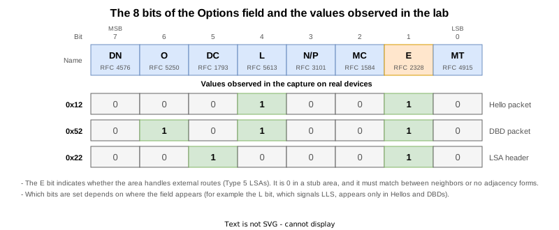
| Bit | Name | Meaning | Defined in |
|---|---|---|---|
| 7 | DN | Prevents routing loops between PE routers in an MPLS VPN. A PE sets it in the LSAs it advertises to a CE, and a PE that receives an LSA with this bit set does not re-advertise that LSA into the VPN. | RFC 4576 |
| 6 | O | Indicates support for Opaque LSAs (Types 9/10/11). Used by the OSPF TE extensions and by Segment Routing. | RFC 5250 |
| 5 | DC | Indicates support for demand circuits (links such as ISDN that are only connected when needed). RFC 4577 also requires a sham link in an MPLS VPN to be treated as a demand circuit, so this bit is still in use today. | RFC 1793 |
| 4 | L | Indicates that an LLS (Link-Local Signaling) data block is attached to the packet. RFC 5613 reused the position that RFC 2328 had assigned to the EA bit (External-Attributes-LSAs). | RFC 5613 |
| 3 | N/P | The N bit indicates support for NSSA areas (used in Hellos). The P bit tells the ABR whether to translate a Type 7 LSA into a Type 5 (used in the header of a Type 7 LSA). | RFC 3101 |
| 2 | MC | Indicates support for multicast OSPF (MOSPF). Hardly used today. | RFC 1584 |
| 1 | E | Indicates whether the area can accept external routes (Type 5 LSAs, AS-external LSAs). It is 1 in a normal area and 0 in a stub area or an NSSA. | RFC 2328 |
| 0 | MT | Indicates support for multi-topology routing. This was the T bit for TOS routing in RFC 1583 and was left unassigned in RFC 2328. | RFC 4915 |
Where the Options Field Appears
| Where it appears | Role |
|---|---|
| Hello packet | Tells the routers on the same link which features this router supports and what kind of area this is. If the E bit does not match, no neighbor relationship forms. |
| DBD packet | Tells the router it is about to synchronize the LSDB with which features it supports. |
| LSA header | Carries the capabilities of the router that originated the LSA throughout the area, together with the LSA. |
Even for the same router, the bits that are set differ depending on where the field appears. The following verification on real devices shows those differences.
Verification on Real Devices
Test Environment
Three Cisco IOS XR routers (XRd 26.1.1) are connected in a line, starting with every link in area 0. This is the same topology used in What Is OSPF?.

The test runs in five stages (STEP 0 to 4), changing the area layout along the way. The show output, syslog and running-config collected from all three routers at every STEP, plus the debug ospf 1 hello output, are gathered per STEP under Configurations Used and show Output at the end of the article. The sections below quote only part of them.
| STEP | Change | What it confirms |
|---|---|---|
| 0 | Initial state | All links in area 0; R1-R2-R3 are Full |
| 1 | R2 and R3 moved into area 1 as a stub area | R2 becomes the ABR; the E bit goes to 0 on the R2-R3 link |
| 2 | stub removed on R3 only | E bit mismatch; the R2-R3 adjacency drops |
| 3 | stub put back on R3 | The adjacency recovers |
| 4 | All interfaces returned to area 0 | Back to the initial state (final state) |
During STEP 0, a capture was taken on the R1-R2 link while clear ospf 1 process was run on R1 to re-establish the adjacency. That single capture contains the Options field in all three places: the Hello, the DBD and the LSA header.
The Options Field in a Hello Packet (STEP 0)
Enabling debug ospf 1 hello on R2 shows the Options in the Hellos it sends and receives.
RP/0/RP0/CPU0:R2#debug ospf 1 hello
Sat Sep  5 15:21:57.260 UTC
RP/0/RP0/CPU0:R2#RP/0/RP0/CPU0:Sep  5 15:21:59.508 UTC: ospf[1035]:  Rcv hello from 3.3.3.3 area 0 from GigabitEthernet0/0/0/1 10.2.3.3 (nbr/if state 3/6) vrf default vrfid 0x60000000
RP/0/RP0/CPU0:Sep  5 15:21:59.508 UTC: ospf[1035]: Rcv hello pkt pri 1 options 0x12 lls options 0x1 DR 10.2.3.3 BDR 10.2.3.2 hello 10 dead 40 netmask 255.255.255.0 (nbr_dr 10.2.3.3 nbr_bdr 10.2.3.2)
RP/0/RP0/CPU0:Sep  5 15:21:59.508 UTC: ospf[1035]:  End of hello processing
RP/0/RP0/CPU0:Sep  5 15:22:03.360 UTC: ospf[1035]: Send hello to 224.0.0.5 area 0 on GigabitEthernet0/0/0/1 from 10.2.3.2 (nbr/if state 3/6)
RP/0/RP0/CPU0:Sep  5 15:22:03.360 UTC: ospf[1035]: Send hello pkt pri 1 options 0x12 DR 10.2.3.3 BDR 10.2.3.2 hello 10 dead 40 netmask 255.255.255.0, vrf default vrfid 0x60000000
RP/0/RP0/CPU0:Sep  5 15:22:03.360 UTC: ospf[1035]:  Extended options bit out 0x1, GigabitEthernet0/0/0/1 (lls_len 32 bytes)
RP/0/RP0/CPU0:Sep  5 15:22:03.544 UTC: ospf[1035]: Send hello to 224.0.0.5 area 0 on GigabitEthernet0/0/0/0 from 10.1.2.2 (nbr/if state 3/5)
Both the sent and the received Hellos carry options 0x12. Opening No.18 of the capture (the Hello R1 sent) shows the breakdown bit by bit.
    OSPF Hello Packet
        Network Mask: 255.255.255.0
        Hello Interval [sec]: 10
        Options: 0x12, (L) LLS Data block, (E) External Routing
            0... .... = DN: Not set
            .0.. .... = (O) Opaque: Not set
            ..0. .... = (DC) Demand Circuits: Not supported
            ...1 .... = (L) LLS Data block: Present
            .... 0... = (N) NSSA: Not supported
            .... .0.. = (MC) Multicast: Not capable
            .... ..1. = (E) External Routing: Capable
            .... ...0 = (MT) Multi-Topology Routing: No
        Router Priority: 1
        Router Dead Interval [sec]: 40
        Designated Router: 10.1.2.2
        Backup Designated Router: 10.1.2.1
        Active Neighbor: 2.2.2.2
    OSPF LLS Data Block
        Checksum: 0x7fc2
        LLS Data Length: 32 bytes
        Extended options TLV
            TLV Type: 1
            TLV Length: 4
            Options: 0x00000001, (LR) LSDB Resynchronization
                .... .... .... .... .... .... .... ..0. = (RS) Restart Signal: Not set
.... .... .... .... .... .... .... ...1 = (LR) LSDB Resynchronization: Set0x12 is 0001 0010, so the bits that are set are L (0x10) and E (0x02).
- L (0x10): indicates that an LLS data block is attached to this Hello. The
OSPF LLS Data Blockbelow is that block, 32 bytes of it. TheExtended options bit out 0x1, ... (lls_len 32 bytes)line in the debug output says the same thing. Note that theOptions: 0x00000001, (LR) LSDB Resynchronizationinside it is a field of the LLS data block itself, not the OSPF Options field. Thells options 0x1in the debug output refers to that one as well. - E (0x02): area 0 is a normal area, so this bit is set to say that external routes can be accepted.
Note also that the O bit and the DC bit are not set. RFC 5250 restricts the O bit to DBDs, so it never appears in a Hello. The DC bit does appear in Hellos, but RFC 1793 Section 3.2.1 defines it as being set on Hellos and DBDs sent out a demand interface, and there is no demand circuit in this setup.
The Options Field a DBD Packet Carries (STEP 0)
The Options from a DBD packet is kept as neighbor information. It is the Options field of show ospf neighbor detail.
RP/0/RP0/CPU0:R2#show ospf neighbor detail
Sat Sep  5 15:23:12.597 UTC

* Indicates MADJ interface
# Indicates Neighbor awaiting BFD session up

Neighbors for OSPF 1

 Neighbor 1.1.1.1, interface address 10.1.2.1
    In the area 0 via interface GigabitEthernet0/0/0/0
    Neighbor priority is 1, State is FULL, 12 state changes
    DR is 10.1.2.2 BDR is 10.1.2.1
    Options is 0x52
    LLS Options is 0x1 (LR)
    Dead timer due in 00:00:37
    Neighbor is up for 00:02:35
No.6 of the capture is the first DBD sent by that same R1.
    OSPF DB Description
        Interface MTU: 1500
        Options: 0x52, (O) Opaque, (L) LLS Data block, (E) External Routing
            0... .... = DN: Not set
            .1.. .... = (O) Opaque: Set
            ..0. .... = (DC) Demand Circuits: Not supported
            ...1 .... = (L) LLS Data block: Present
            .... 0... = (N) NSSA: Not supported
            .... .0.. = (MC) Multicast: Not capable
            .... ..1. = (E) External Routing: Capable
            .... ...0 = (MT) Multi-Topology Routing: No
        DB Description: 0x07, (I) Init, (M) More, (MS) Master
            .... 0... = (R) OOBResync: Not set
            .... .1.. = (I) Init: Set
            .... ..1. = (M) More: Set
            .... ...1 = (MS) Master: Yes
DD Sequence: 19336875450x52 is 0101 0010, so O (0x40), L (0x10) and E (0x02) are set. The same R1 is sending both, yet the O bit is set here and not in the Hello’s 0x12.
O (0x40) indicates support for Opaque LSAs (Types 9/10/11). RFC 5250 states that a neighbor is opaque-capable if and only if it sets the O bit in its Database Description packets, and that the bit should not be set in, and must be ignored when received in, packets other than DBDs. That is why it is not set in the Hello.
The Options Field in an LSA Header (STEP 0)
The Options field of an LSA header is inside the LSA headers carried by LSU, LSAck and DBD packets. No.14 is the LSU in which R1 sends its own Router-LSA.
    LS Update Packet
        Number of LSAs: 1
        LSA-type 1 (Router-LSA), len 48
            .000 0000 0000 1010 = LS Age (seconds): 10
            0... .... .... .... = Do Not Age Flag: 0
            Options: 0x22, (DC) Demand Circuits, (E) External Routing
                0... .... = DN: Not set
                .0.. .... = (O) Opaque: Not set
                ..1. .... = (DC) Demand Circuits: Supported
                ...0 .... = (L) LLS Data block: Not Present
                .... 0... = (N) NSSA: Not supported
                .... .0.. = (MC) Multicast: Not capable
                .... ..1. = (E) External Routing: Capable
                .... ...0 = (MT) Multi-Topology Routing: No
            LS Type: Router-LSA (1)
            Link State ID: 1.1.1.1
            Advertising Router: 1.1.1.1
            Sequence Number: 0x80000001
            Checksum: 0x5bac
Length: 480x22 is 0010 0010, which is DC (0x20) and E (0x02). The O and L bits that were set in the DBD are gone, and DC is set instead.
DC (0x20) indicates support for demand circuits. In an LSA header the bit says that the LSA may be treated as DoNotAge, and RFC 1793 has a router that supports demand circuits set it in every LSA it originates, which is why it is set here even though there is no demand circuit. In Hellos and DBDs the same bit is used to negotiate Hello suppression, so it is only set on a demand interface. Demand circuits themselves belong to the ISDN era, but RFC 4577 Section 4.2.7.3 requires a sham link in an MPLS VPN to be treated as a demand circuit, so this bit is still in use today.
How the Three Differ (STEP 0)
The three values taken from the same capture (ospf-options.pcap) are summarized below.
| No. | Where it appears | Value | Bits set |
|---|---|---|---|
| 18 | Hello packet | 0x12 | L, E |
| 6 | DBD packet | 0x52 | O, L, E |
| 14 | LSA header (inside an LSU) | 0x22 | DC, E |
The same router sends all three, and the values differ because each bit describes information at a different scope.
- L says whether an LLS data block is attached to the packet, so it appears in Hellos and DBDs but not in the header of an LSA stored in the LSDB.
- O is restricted to DBDs by RFC 5250, so it only appears there.
- DC says whether the LSA can be treated as DoNotAge, so it is always set in an LSA header, while in Hellos and DBDs it is only set on a demand interface.
- The only bit set in all three places is the E bit.
Note that show ospf database on IOS XR prints the Options of an LSA header as text rather than hex. Only the DC and MT bits are shown, so the value of the E bit cannot be read from this output.
RP/0/RP0/CPU0:R2#show ospf database router
Sat Sep  5 15:23:13.897 UTC


            OSPF Router with ID (2.2.2.2) (Process ID 1)

		Router Link States (Area 0)

  Routing Bit Set on this LSA
  LS age: 157
  Options: (No TOS-capability, DC)
  LS Type: Router Links
  Link State ID: 1.1.1.1
  Advertising Router: 1.1.1.1
  LS Seq Number: 80000002
  Checksum: 0xb542
  Length: 48
   Number of Links: 2
The E Bit Becomes 0 in a Stub Area (STEP 1)
To see what the E bit means, the R2-R3 link is moved into area 1 and made a stub area. R2 becomes the ABR (area border router).

router ospf 1
 area 0
  no interface GigabitEthernet0/0/0/1
 !
 area 1
  stub
  interface GigabitEthernet0/0/0/1
 !
!
On R3 every interface is moved into area 1 and stub is configured as well. With that in place, the Hellos R2 handles differ per interface.
RP/0/RP0/CPU0:R2#debug ospf 1 hello
Sat Sep  5 15:25:47.485 UTC
RP/0/RP0/CPU0:R2#RP/0/RP0/CPU0:Sep  5 15:25:49.064 UTC: ospf[1035]: Send hello to 224.0.0.5 area 0 on GigabitEthernet0/0/0/0 from 10.1.2.2 (nbr/if state 3/5)
RP/0/RP0/CPU0:Sep  5 15:25:49.064 UTC: ospf[1035]: Send hello pkt pri 1 options 0x12 DR 10.1.2.2 BDR 10.1.2.1 hello 10 dead 40 netmask 255.255.255.0, vrf default vrfid 0x60000000
RP/0/RP0/CPU0:Sep  5 15:25:49.064 UTC: ospf[1035]:  Extended options bit out 0x1, GigabitEthernet0/0/0/0 (lls_len 32 bytes)
RP/0/RP0/CPU0:Sep  5 15:25:49.612 UTC: ospf[1035]:  Rcv hello from 3.3.3.3 area 1 from GigabitEthernet0/0/0/1 10.2.3.3 (nbr/if state 3/6) vrf default vrfid 0x60000000
RP/0/RP0/CPU0:Sep  5 15:25:49.613 UTC: ospf[1035]: Rcv hello pkt pri 1 options 0x10 lls options 0x1 DR 10.2.3.3 BDR 10.2.3.2 hello 10 dead 40 netmask 255.255.255.0 (nbr_dr 10.2.3.3 nbr_bdr 10.2.3.2)
RP/0/RP0/CPU0:Sep  5 15:25:49.613 UTC: ospf[1035]:  End of hello processing
RP/0/RP0/CPU0:Sep  5 15:25:53.159 UTC: ospf[1035]:  Rcv hello from 1.1.1.1 area 0 from GigabitEthernet0/0/0/0 10.1.2.1 (nbr/if state 3/5) vrf default vrfid 0x60000000
RP/0/RP0/CPU0:Sep  5 15:25:53.159 UTC: ospf[1035]: Rcv hello pkt pri 1 options 0x12 lls options 0x1 DR 10.1.2.2 BDR 10.1.2.1 hello 10 dead 40 netmask 255.255.255.0 (nbr_dr 10.1.2.2 nbr_bdr 10.1.2.1)
RP/0/RP0/CPU0:Sep  5 15:25:53.159 UTC: ospf[1035]:  End of hello processing
RP/0/RP0/CPU0:Sep  5 15:25:55.206 UTC: ospf[1035]: Send hello to 224.0.0.5 area 1 on GigabitEthernet0/0/0/1 from 10.2.3.2 (nbr/if state 3/6)
The same R2 handles 0x12 on the area 0 side (Gi0/0/0/0) and 0x10 on the stub area side (Gi0/0/0/1). The only difference is the E bit (0x02). A stub area does not carry external routes (Type 5 LSAs), so the E bit is 0.
The capture on the R2-R3 link (ospf-options-stub.pcap) spans the change from area 0 to the area 1 stub area. No.8 is a Hello R2 sent after the change.
    OSPF Hello Packet
        Network Mask: 255.255.255.0
        Hello Interval [sec]: 10
        Options: 0x10, (L) LLS Data block
            0... .... = DN: Not set
            .0.. .... = (O) Opaque: Not set
            ..0. .... = (DC) Demand Circuits: Not supported
            ...1 .... = (L) LLS Data block: Present
            .... 0... = (N) NSSA: Not supported
            .... .0.. = (MC) Multicast: Not capable
            .... ..0. = (E) External Routing: Not capable
            .... ...0 = (MT) Multi-Topology Routing: No
Router Priority: 1The E bit drops out of the DBD and the LSA header in the same way.
    OSPF DB Description
        Interface MTU: 1500
        Options: 0x50, (O) Opaque, (L) LLS Data block
            0... .... = DN: Not set
            .1.. .... = (O) Opaque: Set
            ..0. .... = (DC) Demand Circuits: Not supported
            ...1 .... = (L) LLS Data block: Present
            .... 0... = (N) NSSA: Not supported
            .... .0.. = (MC) Multicast: Not capable
            .... ..0. = (E) External Routing: Not capable
.... ...0 = (MT) Multi-Topology Routing: No LSA-type 1 (Router-LSA), len 36
.000 0000 0010 1100 = LS Age (seconds): 44
0... .... .... .... = Do Not Age Flag: 0
Options: 0x20, (DC) Demand Circuits
0... .... = DN: Not set
.0.. .... = (O) Opaque: Not set
..1. .... = (DC) Demand Circuits: Supported
...0 .... = (L) LLS Data block: Not Present
.... 0... = (N) NSSA: Not supported
.... .0.. = (MC) Multicast: Not capable
.... ..0. = (E) External Routing: Not capable
.... ...0 = (MT) Multi-Topology Routing: NoSummarizing how the three values change between area 0 and the stub area:
| Where it appears | Area 0 (STEP 0) | Area 1, stub (STEP 1) | Difference |
|---|---|---|---|
| Hello packet | 0x12 | 0x10 | E |
| DBD packet | 0x52 | 0x50 | E |
| LSA header | 0x22 | 0x20 | E |
The Options in the neighbor information changes the same way.
 Neighbor 3.3.3.3, interface address 10.2.3.3
    In the area 1 via interface GigabitEthernet0/0/0/1
    Neighbor priority is 1, State is FULL, 6 state changes
    DR is 10.2.3.3 BDR is 10.2.3.2
    Options is 0x50
    LLS Options is 0x1 (LR)
The area type can also be confirmed with show ospf.
 Routing Process "ospf 1" with ID 2.2.2.2
 It is an area border router
 Number of areas in this router is 2. 1 normal 1 stub 0 nssa
No Adjacency Forms When the E Bit Does Not Match (STEP 2)
Removing only stub on the R3 side leaves the area number at 1 on both sides and makes just the E bit differ.
router ospf 1
 area 1
  no stub
 !
!
The Hello debug on R2 shows the Hellos from R1 (area 0) being processed normally while the ones from R3 are rejected by validation.
RP/0/RP0/CPU0:R2#debug ospf 1 hello
Sat Sep  5 15:28:38.536 UTC
RP/0/RP0/CPU0:R2#RP/0/RP0/CPU0:Sep  5 15:28:40.103 UTC: ospf[1035]:  Rcv hello from 3.3.3.3 area 1 from GigabitEthernet0/0/0/1 10.2.3.3 (nbr/if state 3/6) vrf default vrfid 0x60000000
RP/0/RP0/CPU0:Sep  5 15:28:40.103 UTC: ospf[1035]:  Hello from 10.2.3.3 with mismatched Stub/Transit area option bit
RP/0/RP0/CPU0:Sep  5 15:28:40.103 UTC: ospf[1035]: hello from 3.3.3.3 area 1 failed validation
RP/0/RP0/CPU0:Sep  5 15:28:45.315 UTC: ospf[1035]:  Rcv hello from 1.1.1.1 area 0 from GigabitEthernet0/0/0/0 10.1.2.1 (nbr/if state 3/5) vrf default vrfid 0x60000000
RP/0/RP0/CPU0:Sep  5 15:28:45.315 UTC: ospf[1035]: Rcv hello pkt pri 1 options 0x12 lls options 0x1 DR 10.1.2.2 BDR 10.1.2.1 hello 10 dead 40 netmask 255.255.255.0 (nbr_dr 10.1.2.2 nbr_bdr 10.1.2.1)
RP/0/RP0/CPU0:Sep  5 15:28:45.315 UTC: ospf[1035]:  End of hello processing
mismatched Stub/Transit area option bit refers to the E bit mismatch. The Hello itself is received, but it is discarded with failed validation, so the neighbor is not maintained and disappears when the Dead interval expires.
RP/0/RP0/CPU0:R2#show ospf neighbor
Sat Sep  5 15:30:24.949 UTC

* Indicates MADJ interface
# Indicates Neighbor awaiting BFD session up

Neighbors for OSPF 1

Neighbor ID     Pri   State           Dead Time   Address         Interface
1.1.1.1         1     FULL/BDR        00:00:34    10.1.2.1        GigabitEthernet0/0/0/0
    Neighbor is up for 00:09:47

Total neighbor count: 1
All the syslog records is dead timer expired.
RP/0/RP0/CPU0:Sep 5 15:29:00.654 UTC: ospf[1035]: %ROUTING-OSPF-5-ADJCHG : Process 1, Nbr 3.3.3.3 on GigabitEthernet0/0/0/1 in area 1 from FULL to DOWN, Neighbor Down: dead timer expired, vrf default vrfid 0x60000000 show ospf statistics interface either. When the Hellos arrive but the neighbor disappears, you have to go down to debug ospf 1 hello to find the cause.After this, stub was put back on R3 to recover the adjacency (STEP 3), and finally every interface was returned to area 0 to restore the initial state (STEP 4).
The two full captures are these.
Download the capture on the R1-R2 link (ospf-options.pcap)
Download the capture on the R2-R3 link (ospf-options-stub.pcap)
Configurations Used and show Output
At every STEP the following four files were collected from each of the three routers. The ..._run.txt files are the configurations used (the final state is the one from STEP 4).
| File | Contents |
|---|---|
..._show.txt | show version / show interface description / show route / show route ospf / show ospf / show ospf interface / show ospf interface brief / show ospf neighbor / show ospf neighbor detail / show ospf database / show ospf database router / show ospf database network / show ospf statistics interface |
..._log.txt | show logging narrowed to that STEP. A marker is written with logmsg at the start of each STEP and its timestamp passed to show logging start (STEP 0 alone holds the whole history since boot). |
..._run.txt | show running-config at that STEP (that is, the configuration used at that STEP) |
..._debug.txt | debug ospf 1 hello output, collected separately for the article (R2 only, STEP 0 to 2) |
STEP 0: initial state - all links in area 0; R1-R2-R3 are Full
| Router | show output | syslog | running-config | debug |
|---|---|---|---|---|
| R1 | show | log | run | - |
| R2 | show | log | run | debug |
| R3 | show | log | run | - |
STEP 1: R2 and R3 moved into area 1 as a stub area - R2 becomes the ABR; the E bit goes to 0 on the R2-R3 link
| Router | show output | syslog | running-config | debug |
|---|---|---|---|---|
| R1 | show | log | run | - |
| R2 | show | log | run | debug |
| R3 | show | log | run | - |
STEP 2: stub removed on R3 only - E bit mismatch; the R2-R3 adjacency drops
| Router | show output | syslog | running-config | debug |
|---|---|---|---|---|
| R1 | show | log | run | - |
| R2 | show | log | run | debug |
| R3 | show | log | run | - |
STEP 3: stub put back on R3 - the adjacency recovers
| Router | show output | syslog | running-config | debug |
|---|---|---|---|---|
| R1 | show | log | run | - |
| R2 | show | log | run | - |
| R3 | show | log | run | - |
STEP 4: all interfaces returned to area 0 (final state) - back to the initial state
| Router | show output | syslog | running-config | debug |
|---|---|---|---|---|
| R1 | show | log | run | - |
| R2 | show | log | run | - |
| R3 | show | log | run | - |
How a stub area itself behaves is covered in OSPF stub and totally stubby areas.
References
| RFC | Title | Summary |
|---|---|---|
| RFC 2328 | OSPF Version 2 | The Options field is defined in Appendix A.2, which assigns the E, MC, N/P, EA and DC bits and describes only the E bit completely. |
| RFC 1584 | Multicast Extensions to OSPF | The MC bit. |
| RFC 1793 | Extending OSPF to Support Demand Circuits | The DC bit. |
| RFC 3101 | The OSPF Not-So-Stubby Area (NSSA) Option | The N/P bit. |
| RFC 4576 | Using a Link State Advertisement (LSA) Options Bit to Prevent Looping in BGP/MPLS IP VPNs | The DN bit. |
| RFC 4577 | OSPF as the Provider/Customer Edge Protocol for BGP/MPLS IP VPNs | Section 4.2.7.3 requires sham links to be treated as demand circuits. |
| RFC 4915 | Multi-Topology (MT) Routing in OSPF | The MT bit. |
| RFC 5250 | The OSPF Opaque LSA Option | The O bit. |
| RFC 5613 | OSPF Link-Local Signaling | The L bit. |
Related Articles
- What is OSPF
- OSPF Router ID
- OSPF Behavior When Router IDs Collide
- OSPF Packet Types and Header Format
- OSPF Authentication
- OSPF Neighbor States
- OSPF Options Field
- OSPF DR and BDR
- OSPF Network Types
- OSPF Cost (Metric)
- OSPF Equal-Cost Multi-Path (ECMP)
- OSPF External Routes (Redistributing Static Routes)
- OSPF RFC1583 Compatibility (External Route Selection Rules)
- OSPF Forwarding Address of AS External Routes
- OSPF Multiple Areas and the ABR
- OSPF Virtual Links
- OSPF Stub and Totally Stubby Areas
- OSPF NSSA and Totally NSSA
- OSPF Default Route
- OSPF Route Summarization
- OSPF LSAs and the LSA Header
- OSPF Hello and Dead Intervals
- OSPF Convergence Timers (SPF / LSA Throttling)
- OSPF LSA Refresh and Pacing
- OSPF router-LSA (type 1)
- OSPF network-LSA (type 2)
- OSPF summary-LSA (type 3)
- OSPF ASBR summary-LSA (type 4)
- OSPF AS external-LSA (type 5)
- OSPF NSSA External-LSA (Type 7)