What a router-LSA is
A router-LSA (type 1) is an LSA in which a router describes nothing but its own doorstep: what it is attached to, inside one area, and at what cost. There is nothing about neighbouring areas and nothing about external routes. Yet collect the router-LSAs of every router in an area and the graph of that area comes back exactly. The shortest-path tree is built from these.
| Item | Content |
|---|---|
| Who originates it | Every router — internal routers, ABRs and ASBRs alike |
| How many | One per area. An ABR with interfaces in two areas originates two |
| How far it travels | Only inside that area; it never crosses an ABR |
| Link State ID | The router ID of the originating router |
| Advertising Router | The same router ID (for type 1 these two always match) |
In this article a seven-router lab is used to change one router (R11) one setting at a time and watch which field of its router-LSA moves. Five kinds of change: the cost, making an interface passive, changing the network type, shutting an interface down, and redistributing.
The 20-byte header common to all LSAs (LS age, sequence number, checksum and so on) is covered in OSPF LSAs and the LSA header. This article is the body that follows it.
Packet format
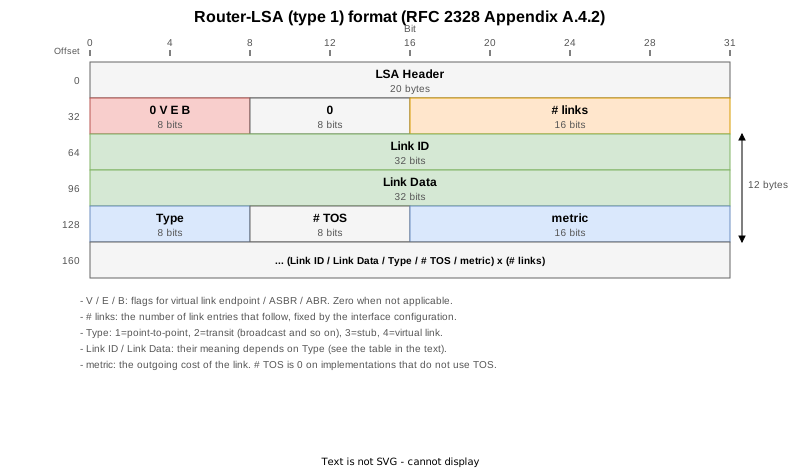
After the 20-byte common header come four bytes of flags plus a link count, and then # links link entries of 12 bytes each. An entry holds five things.
| Field | Size | Content |
|---|---|---|
| Link ID | 4 bytes | What identifies the other end of the link. Its meaning depends on Type |
| Link Data | 4 bytes | Information about the local end. Sometimes an address, sometimes a mask |
| Type | 1 byte | 1=point-to-point, 2=transit, 3=stub, 4=virtual link |
| # TOS | 1 byte | The number of per-TOS metrics. Always 0 on current implementations |
| metric | 2 bytes | The outgoing cost of the link |
Link ID and Link Data are the same four-byte slot, yet what goes into them depends on Type. That is the first hurdle in reading a router-LSA.
Lab topology

| Router | Area | Interfaces | Network type |
|---|---|---|---|
| R1 | 1 | Lo0 1.1.1.1/32, Gi0/0/0/0 10.0.12.1/24 | point-to-point |
| R2 | 0 / 1 | Lo0 2.2.2.2/32, Gi0/0/0/1 10.0.23.2/24, Gi0/0/0/2 10.0.24.2/24 (area 0), Gi0/0/0/0 10.0.12.2/24 (area 1) | Gi0/0/0/1 only is broadcast |
| R3 | 0 / 2 | Lo0 3.3.3.3/32, Gi0/0/0/0 10.0.23.3/24 (area 0), Gi0/0/0/1 172.16.3.3/24 (area 2) | Gi0/0/0/0 only is broadcast |
| R4 | 0 / 2 | Lo0 4.4.4.4/32, Gi0/0/0/0 10.0.24.4/24 (area 0), Gi0/0/0/1 172.16.4.4/24 (area 2, cost 10) | all point-to-point |
| R11 | 2 | Lo0 11.11.11.11/32, Gi0/0/0/0 172.16.3.11/24, Gi0/0/0/1 10.1.11.11/24 | Gi0/0/0/1 only is broadcast |
| R12 | 2 | Lo0 12.12.12.12/32, Gi0/0/0/0 172.16.4.12/24 (cost 10), Gi0/0/0/1 10.1.12.12/24 | all point-to-point |
| R13 | 2 | Lo0 13.13.13.13/32, Gi0/0/0/0 10.1.11.13/24, Gi0/0/0/1 10.1.12.13/24 | Gi0/0/0/0 only is broadcast |
R11 is the protagonist because all three kinds of router-LSA entry meet on one router: a loopback (stub), a point-to-point link to R3 (PTP plus stub) and a broadcast segment with R13 (transit), all in one LSA. And because R11 is an internal router of area 2, the link entries can be watched without the ABR and ASBR flags getting in the way.
R11 has three interfaces.
RP/0/RP0/CPU0:R11#show ospf interface brief
Tue Sep  8 05:45:17.745 UTC

* Indicates MADJ interface, (P) Indicates fast detect hold down state

Interfaces for OSPF 1

Interface          PID   Area            IP Address/Mask    Cost  State Nbrs F/C
Lo0                1     2               11.11.11.11/32     1     LOOP  0/0
Gi0/0/0/0          1     2               172.16.3.11/24     1     P2P   1/1
Gi0/0/0/1          1     2               10.1.11.11/24      1     BDR   1/1
Each STEP, what it changes and what it confirms. Only R11 is reconfigured.
| STEP | Change | What it confirms |
|---|---|---|
| 0 | Right after boot | Four entries: loopback (Stub), p2p (PTP + Stub), broadcast (Transit) |
| 1 | cost 5 on Gi0/0/0/1 | Only the Transit entry’s metric moves |
| 2 | Cost restored | The contents come back but the sequence number stays advanced |
| 3 | passive enable on Gi0/0/0/1 | A broadcast interface with no full adjacency becomes Stub; R13’s Network-LSA disappears |
| 4 | passive removed | Recovery |
| 5 | R11 - R3 changed to broadcast | PTP + Stub collapse into one Transit and R11 originates a Network-LSA |
| 6 | Back to point-to-point | Recovery |
| 7 | shutdown on Gi0/0/0/0 | Both entries for that interface disappear; R3 on the far side keeps only the Stub |
| 8 | Restored and a static redistributed | The links are unchanged; the E bit appears in the flags |
How many entries does one interface become?
RFC 2328 section 12.4.1 fixes the mapping, and there are only four cases.
| State of the interface | Entries produced | Link ID | Link Data |
|---|---|---|---|
| Loopback | one stub | the address of the loopback | 255.255.255.255 (a host mask) |
| Point-to-point with a FULL adjacency | two: a PTP and a stub | PTP: the neighbour’s router ID; stub: the subnet number | PTP: the router’s own interface address; stub: the subnet mask |
| Broadcast with a FULL adjacency | one transit | the interface address of the DR | the router’s own interface address |
| Passive, or broadcast with no adjacency at all | one stub | the subnet number | the subnet mask |

On the device, show ospf database router self-originate prints only the router-LSA this router originated.
RP/0/RP0/CPU0:R11#show ospf database router self-originate
Tue Sep  8 05:45:22.297 UTC


            OSPF Router with ID (11.11.11.11) (Process ID 1)

		Router Link States (Area 2)

  LS age: 163
  Options: (No TOS-capability, DC)
  LS Type: Router Links
  Link State ID: 11.11.11.11
  Advertising Router: 11.11.11.11
  LS Seq Number: 80000004
  Checksum: 0xc1d7
  Length: 72
   Number of Links: 4

    Link connected to: a Stub Network
     (Link ID) Network/subnet number: 11.11.11.11
     (Link Data) Network Mask: 255.255.255.255
      Number of TOS metrics: 0
       TOS 0 Metrics: 1

    Link connected to: another Router (point-to-point)
     (Link ID) Neighboring Router ID: 3.3.3.3
     (Link Data) Router Interface address: 172.16.3.11
      Number of TOS metrics: 0
       TOS 0 Metrics: 1

    Link connected to: a Stub Network
     (Link ID) Network/subnet number: 172.16.3.0
     (Link Data) Network Mask: 255.255.255.0
      Number of TOS metrics: 0
       TOS 0 Metrics: 1

    Link connected to: a Transit Network
     (Link ID) Designated Router address: 10.1.11.13
     (Link Data) Router Interface address: 10.1.11.11
      Number of TOS metrics: 0
       TOS 0 Metrics: 1
Each entry lines up with the figure.
| Entry | Interface it came from | Link ID | Link Data |
|---|---|---|---|
| 1. stub | Lo0 11.11.11.11/32 | 11.11.11.11 (the loopback address) | 255.255.255.255 |
| 2. PTP | Gi0/0/0/0 172.16.3.11/24 (point-to-point) | 3.3.3.3 (the neighbour’s router ID, not an address) | 172.16.3.11 (its own address) |
| 3. stub | the subnet of the same Gi0/0/0/0 | 172.16.3.0 (the subnet number) | 255.255.255.0 (the mask) |
| 4. transit | Gi0/0/0/1 10.1.11.11/24 (broadcast, R13 is the DR) | 10.1.11.13 (the DR’s address, not its own) | 10.1.11.11 (its own address) |
A point-to-point link becoming two entries is the part that trips people up. Entry 2 is the edge of the SPF graph (R11 can reach R3) and entry 3 is the IP subnet on that link (172.16.3.0/24 as a destination). RFC 2328 section 12.4.1.1 requires both for a numbered point-to-point link. A broadcast link produces only entry 4, because the subnet information lives in the network-LSA (type 2) that the DR originates.
Seen from the capture, Link Type shows up as a number. This is packet No.97, taken on the R11 - R13 segment.
Open Shortest Path First
    OSPF Header
        Version: 2
        Message Type: LS Update (4)
        Packet Length: 100
        Source OSPF Router: 11.11.11.11
        Area ID: 0.0.0.2
        Checksum: 0xa8bc [correct]
        Instance ID: Base IPv4 Unicast Instance (0)
        Auth Type: Null (0)
        Auth Data (none): 0000000000000000
    LS Update Packet
        Number of LSAs: 1
        LSA-type 1 (Router-LSA), len 72
            .000 0000 0000 0001 = LS Age (seconds): 1
            0... .... .... .... = Do Not Age Flag: 0
            Options: 0x28, (DC) Demand Circuits, (N) NSSA
                0... .... = DN: Not set
                .0.. .... = (O) Opaque: Not set
                ..1. .... = (DC) Demand Circuits: Supported
                ...0 .... = (L) LLS Data block: Not Present
                .... 1... = (N) NSSA: Supported
                .... .0.. = (MC) Multicast: Not capable
                .... ..0. = (E) External Routing: Not capable
                .... ...0 = (MT) Multi-Topology Routing: No
            LS Type: Router-LSA (1)
            Link State ID: 11.11.11.11
            Advertising Router: 11.11.11.11
            Sequence Number: 0x80000006
            Checksum: 0xbdd9
            Length: 72
            Flags: 0x00
                0... .... = (H) Host: No
                ..0. .... = (S) Shortcut-capable ABR: No
                ...0 .... = (N) NSSA translation: No
                .... 0... = (W) Wild-card multicast receiver: No
                .... .0.. = (V) Virtual link endpoint: No
                .... ..0. = (E) AS boundary router: No
                .... ...0 = (B) Area border router: No
            Number of Links: 4
            Type: Stub     ID: 11.11.11.11     Data: 255.255.255.255 Metric: 1
                Link ID: 11.11.11.11 - IP network/subnet number
                Link Data: 255.255.255.255
                Link Type: 3 - Connection to a stub network
                Number of Metrics: 0 - TOS
                0 Metric: 1
            Type: PTP      ID: 3.3.3.3         Data: 172.16.3.11     Metric: 1
                Link ID: 3.3.3.3 - Neighboring router's Router ID
                Link Data: 172.16.3.11
                Link Type: 1 - Point-to-point connection to another router
                Number of Metrics: 0 - TOS
                0 Metric: 1
            Type: Stub     ID: 172.16.3.0      Data: 255.255.255.0   Metric: 1
                Link ID: 172.16.3.0 - IP network/subnet number
                Link Data: 255.255.255.0
                Link Type: 3 - Connection to a stub network
                Number of Metrics: 0 - TOS
                0 Metric: 1
            Type: Transit  ID: 10.1.11.13      Data: 10.1.11.11      Metric: 1
                Link ID: 10.1.11.13 - IP address of Designated Router
                Link Data: 10.1.11.11
                Link Type: 2 - Connection to a transit network
                Number of Metrics: 0 - TOS
0 Metric: 1Type: Stub, PTP and Transit appear side by side, along with Link Type: 3, 1 and 2. What the CLI spelled out as “a Stub Network”, “another Router (point-to-point)” and “a Transit Network” is this single byte on the wire.
Which field moves when the configuration changes
This is the heart of the article. R11’s configuration was changed one item at a time and its router-LSA collected each time. Across the nine STEPs:
| STEP | Change | Seq | # links | Entries |
|---|---|---|---|---|
| 0 | right after boot | 80000004 | 4 | stub 11.11.11.11 / PTP 3.3.3.3 / stub 172.16.3.0 / transit 10.1.11.13 |
| 1 | cost 5 on Gi0/0/0/1 | 80000005 | 4 | as above (only the transit metric goes 1 to 5) |
| 2 | cost reverted | 80000006 | 4 | same as STEP 0 |
| 3 | passive enable on Gi0/0/0/1 | 80000007 | 4 | stub / PTP / stub / stub 10.1.11.0 |
| 4 | passive removed | 80000008 | 4 | same as STEP 0 |
| 5 | R11 - R3 made broadcast | 8000000a | 3 | stub / transit 172.16.3.11 / transit 10.1.11.13 |
| 6 | back to point-to-point | 8000000c | 4 | same as STEP 0 |
| 7 | shutdown on Gi0/0/0/0 | 8000000d | 2 | stub 11.11.11.11 / transit 10.1.11.13 |
| 8 | interface restored, static redistributed | 8000000f | 4 | same as STEP 0, plus the E bit in the flags |
The sequence numbers skip — 80000009, 8000000b and 8000000e never appear in the table. Those were consumed by intermediate states: in STEP 5, for instance, the LSA was regenerated once when the network type changed and once more when the DR was elected. A sequence number counts regenerations, not configuration changes.
The larger changes follow, one by one.
Changing the cost: only the metric moves
With cost 5 applied, only TOS 0 Metrics in the transit entry goes from 1 to 5.
RP/0/RP0/CPU0:R11#show ospf database router self-originate
Tue Sep  8 05:49:17.947 UTC


            OSPF Router with ID (11.11.11.11) (Process ID 1)

		Router Link States (Area 2)

  LS age: 163
  Options: (No TOS-capability, DC)
  LS Type: Router Links
  Link State ID: 11.11.11.11
  Advertising Router: 11.11.11.11
  LS Seq Number: 80000005
  Checksum: 0x98fb
  Length: 72
   Number of Links: 4

    Link connected to: a Stub Network
     (Link ID) Network/subnet number: 11.11.11.11
     (Link Data) Network Mask: 255.255.255.255
      Number of TOS metrics: 0
       TOS 0 Metrics: 1

    Link connected to: another Router (point-to-point)
     (Link ID) Neighboring Router ID: 3.3.3.3
     (Link Data) Router Interface address: 172.16.3.11
      Number of TOS metrics: 0
       TOS 0 Metrics: 1

    Link connected to: a Stub Network
     (Link ID) Network/subnet number: 172.16.3.0
     (Link Data) Network Mask: 255.255.255.0
      Number of TOS metrics: 0
       TOS 0 Metrics: 1

    Link connected to: a Transit Network
     (Link ID) Designated Router address: 10.1.11.13
     (Link Data) Router Interface address: 10.1.11.11
      Number of TOS metrics: 0
       TOS 0 Metrics: 5
The entries keep their order and their number. The metric is two bytes inside an entry, so it does not affect the structure. What did change is LS Seq Number (80000004 to 80000005), the Checksum, and LS age going back to 0.
STEP 2 puts the cost back, and the entries return to what they were in STEP 0 — but the sequence number stays at 80000006 and does not go back. Newer-versus-older is decided by the sequence number alone, so winding it back would make the LSA look older than the one already flooded.
Making it passive: the transit entry becomes a stub
passive enable stops Hello on the segment and the adjacency goes away. RFC 2328 section 12.4.1.2 says that a broadcast interface with no full adjacency is advertised as a stub network, and the device does exactly that.
RP/0/RP0/CPU0:R11#show ospf database router self-originate
Tue Sep  8 05:57:29.346 UTC


            OSPF Router with ID (11.11.11.11) (Process ID 1)

		Router Link States (Area 2)

  LS age: 186
  Options: (No TOS-capability, DC)
  LS Type: Router Links
  Link State ID: 11.11.11.11
  Advertising Router: 11.11.11.11
  LS Seq Number: 80000007
  Checksum: 0x497a
  Length: 72
   Number of Links: 4

    Link connected to: a Stub Network
     (Link ID) Network/subnet number: 11.11.11.11
     (Link Data) Network Mask: 255.255.255.255
      Number of TOS metrics: 0
       TOS 0 Metrics: 1

    Link connected to: another Router (point-to-point)
     (Link ID) Neighboring Router ID: 3.3.3.3
     (Link Data) Router Interface address: 172.16.3.11
      Number of TOS metrics: 0
       TOS 0 Metrics: 1

    Link connected to: a Stub Network
     (Link ID) Network/subnet number: 172.16.3.0
     (Link Data) Network Mask: 255.255.255.0
      Number of TOS metrics: 0
       TOS 0 Metrics: 1

    Link connected to: a Stub Network
     (Link ID) Network/subnet number: 10.1.11.0
     (Link Data) Network Mask: 255.255.255.0
      Number of TOS metrics: 0
       TOS 0 Metrics: 1
Entry 4 changed from a Transit Network to a Stub Network, its Link ID from 10.1.11.13 (the DR’s address) to 10.1.11.0 (the subnet number), and its Link Data from 10.1.11.11 (its own address) to 255.255.255.0 (the mask) — all at once. No interface went away, so the number of entries is still 4.
The packet shows the same thing.
Open Shortest Path First
    OSPF Header
        Version: 2
        Message Type: LS Update (4)
        Packet Length: 100
        Source OSPF Router: 11.11.11.11
        Area ID: 0.0.0.2
        Checksum: 0x3233 [correct]
        Instance ID: Base IPv4 Unicast Instance (0)
        Auth Type: Null (0)
        Auth Data (none): 0000000000000000
    LS Update Packet
        Number of LSAs: 1
        LSA-type 1 (Router-LSA), len 72
            .000 0000 0000 0001 = LS Age (seconds): 1
            0... .... .... .... = Do Not Age Flag: 0
            Options: 0x28, (DC) Demand Circuits, (N) NSSA
                0... .... = DN: Not set
                .0.. .... = (O) Opaque: Not set
                ..1. .... = (DC) Demand Circuits: Supported
                ...0 .... = (L) LLS Data block: Not Present
                .... 1... = (N) NSSA: Supported
                .... .0.. = (MC) Multicast: Not capable
                .... ..0. = (E) External Routing: Not capable
                .... ...0 = (MT) Multi-Topology Routing: No
            LS Type: Router-LSA (1)
            Link State ID: 11.11.11.11
            Advertising Router: 11.11.11.11
            Sequence Number: 0x80000007
            Checksum: 0x497a
            Length: 72
            Flags: 0x00
                0... .... = (H) Host: No
                ..0. .... = (S) Shortcut-capable ABR: No
                ...0 .... = (N) NSSA translation: No
                .... 0... = (W) Wild-card multicast receiver: No
                .... .0.. = (V) Virtual link endpoint: No
                .... ..0. = (E) AS boundary router: No
                .... ...0 = (B) Area border router: No
            Number of Links: 4
            Type: Stub     ID: 11.11.11.11     Data: 255.255.255.255 Metric: 1
                Link ID: 11.11.11.11 - IP network/subnet number
                Link Data: 255.255.255.255
                Link Type: 3 - Connection to a stub network
                Number of Metrics: 0 - TOS
                0 Metric: 1
            Type: PTP      ID: 3.3.3.3         Data: 172.16.3.11     Metric: 1
                Link ID: 3.3.3.3 - Neighboring router's Router ID
                Link Data: 172.16.3.11
                Link Type: 1 - Point-to-point connection to another router
                Number of Metrics: 0 - TOS
                0 Metric: 1
            Type: Stub     ID: 172.16.3.0      Data: 255.255.255.0   Metric: 1
                Link ID: 172.16.3.0 - IP network/subnet number
                Link Data: 255.255.255.0
                Link Type: 3 - Connection to a stub network
                Number of Metrics: 0 - TOS
                0 Metric: 1
            Type: Stub     ID: 10.1.11.0       Data: 255.255.255.0   Metric: 1
                Link ID: 10.1.11.0 - IP network/subnet number
                Link Data: 255.255.255.0
                Link Type: 3 - Connection to a stub network
                Number of Metrics: 0 - TOS
0 Metric: 1The same thing happens on the other side of the segment. R13 loses its only adjacency on Gi0/0/0/0, so that segment becomes a stub in R13’s router-LSA too. And on top of that,
RP/0/RP0/CPU0:R13#show ospf database network
Tue Sep  8 05:58:13.515 UTC


            OSPF Router with ID (13.13.13.13) (Process ID 1)
the network-LSA is gone altogether. show ospf interface brief still calls R13 the DR, but a DR with no full adjacency does not originate a network-LSA (RFC 2328 section 12.4.2). With only one router on a broadcast segment, that segment is effectively a stub network.
Turning point-to-point into broadcast: two entries collapse into one
Removing network point-to-point from both ends of R11 - R3 turns the “PTP plus stub” pair of a numbered point-to-point link into a single transit entry.
RP/0/RP0/CPU0:R11#show ospf database router self-originate
Tue Sep  8 06:06:42.673 UTC


            OSPF Router with ID (11.11.11.11) (Process ID 1)

		Router Link States (Area 2)

  LS age: 159
  Options: (No TOS-capability, DC)
  LS Type: Router Links
  Link State ID: 11.11.11.11
  Advertising Router: 11.11.11.11
  LS Seq Number: 8000000a
  Checksum: 0xbae9
  Length: 60
   Number of Links: 3

    Link connected to: a Stub Network
     (Link ID) Network/subnet number: 11.11.11.11
     (Link Data) Network Mask: 255.255.255.255
      Number of TOS metrics: 0
       TOS 0 Metrics: 1

    Link connected to: a Transit Network
     (Link ID) Designated Router address: 172.16.3.11
     (Link Data) Router Interface address: 172.16.3.11
      Number of TOS metrics: 0
       TOS 0 Metrics: 1

    Link connected to: a Transit Network
     (Link ID) Designated Router address: 10.1.11.13
     (Link Data) Router Interface address: 10.1.11.11
      Number of TOS metrics: 0
       TOS 0 Metrics: 1
Number of Links went from 4 to 3. The entries are stub 11.11.11.11, transit 172.16.3.11 and transit 10.1.11.13.
The Link ID of the new transit entry is 172.16.3.11 — R11’s own address — because R11 is the DR of that segment.
RP/0/RP0/CPU0:R11#show ospf interface brief
Tue Sep  8 06:06:38.143 UTC

* Indicates MADJ interface, (P) Indicates fast detect hold down state

Interfaces for OSPF 1

Interface          PID   Area            IP Address/Mask    Cost  State Nbrs F/C
Lo0                1     2               11.11.11.11/32     1     LOOP  0/0
Gi0/0/0/0          1     2               172.16.3.11/24     1     DR    1/1
Gi0/0/0/1          1     2               10.1.11.11/24      1     BDR   1/1
R11’s router ID 11.11.11.11 beats R3’s 3.3.3.3, so R11 won the election. As a result R11 originates a new network-LSA.
Open Shortest Path First
    OSPF Header
        Version: 2
        Message Type: LS Update (4)
        Packet Length: 60
        Source OSPF Router: 11.11.11.11
        Area ID: 0.0.0.2
        Checksum: 0xeba1 [correct]
        Instance ID: Base IPv4 Unicast Instance (0)
        Auth Type: Null (0)
        Auth Data (none): 0000000000000000
    LS Update Packet
        Number of LSAs: 1
        LSA-type 2 (Network-LSA), len 32
            .000 0000 0000 0001 = LS Age (seconds): 1
            0... .... .... .... = Do Not Age Flag: 0
            Options: 0x28, (DC) Demand Circuits, (N) NSSA
                0... .... = DN: Not set
                .0.. .... = (O) Opaque: Not set
                ..1. .... = (DC) Demand Circuits: Supported
                ...0 .... = (L) LLS Data block: Not Present
                .... 1... = (N) NSSA: Supported
                .... .0.. = (MC) Multicast: Not capable
                .... ..0. = (E) External Routing: Not capable
                .... ...0 = (MT) Multi-Topology Routing: No
            LS Type: Network-LSA (2)
            Link State ID: 172.16.3.11
            Advertising Router: 11.11.11.11
            Sequence Number: 0x80000001
            Checksum: 0x7391
            Length: 32
            Netmask: 255.255.255.0
            Attached Router: 3.3.3.3
Attached Router: 11.11.11.11So one line of configuration removes an entry from the router-LSA and adds a whole LSA in its place. The area ends up with more LSAs while the router-LSA itself gets shorter. Network types are covered in OSPF network types and DR election in DR and BDR.
The router-LSA side shows two transit entries side by side.
Open Shortest Path First
    OSPF Header
        Version: 2
        Message Type: LS Update (4)
        Packet Length: 88
        Source OSPF Router: 11.11.11.11
        Area ID: 0.0.0.2
        Checksum: 0xb2be [correct]
        Instance ID: Base IPv4 Unicast Instance (0)
        Auth Type: Null (0)
        Auth Data (none): 0000000000000000
    LS Update Packet
        Number of LSAs: 1
        LSA-type 1 (Router-LSA), len 60
            .000 0000 0000 0001 = LS Age (seconds): 1
            0... .... .... .... = Do Not Age Flag: 0
            Options: 0x28, (DC) Demand Circuits, (N) NSSA
                0... .... = DN: Not set
                .0.. .... = (O) Opaque: Not set
                ..1. .... = (DC) Demand Circuits: Supported
                ...0 .... = (L) LLS Data block: Not Present
                .... 1... = (N) NSSA: Supported
                .... .0.. = (MC) Multicast: Not capable
                .... ..0. = (E) External Routing: Not capable
                .... ...0 = (MT) Multi-Topology Routing: No
            LS Type: Router-LSA (1)
            Link State ID: 11.11.11.11
            Advertising Router: 11.11.11.11
            Sequence Number: 0x8000000a
            Checksum: 0xbae9
            Length: 60
            Flags: 0x00
                0... .... = (H) Host: No
                ..0. .... = (S) Shortcut-capable ABR: No
                ...0 .... = (N) NSSA translation: No
                .... 0... = (W) Wild-card multicast receiver: No
                .... .0.. = (V) Virtual link endpoint: No
                .... ..0. = (E) AS boundary router: No
                .... ...0 = (B) Area border router: No
            Number of Links: 3
            Type: Stub     ID: 11.11.11.11     Data: 255.255.255.255 Metric: 1
                Link ID: 11.11.11.11 - IP network/subnet number
                Link Data: 255.255.255.255
                Link Type: 3 - Connection to a stub network
                Number of Metrics: 0 - TOS
                0 Metric: 1
            Type: Transit  ID: 172.16.3.11     Data: 172.16.3.11     Metric: 1
                Link ID: 172.16.3.11 - IP address of Designated Router
                Link Data: 172.16.3.11
                Link Type: 2 - Connection to a transit network
                Number of Metrics: 0 - TOS
                0 Metric: 1
            Type: Transit  ID: 10.1.11.13      Data: 10.1.11.11      Metric: 1
                Link ID: 10.1.11.13 - IP address of Designated Router
                Link Data: 10.1.11.11
                Link Type: 2 - Connection to a transit network
                Number of Metrics: 0 - TOS
0 Metric: 1Shutting an interface down: two entries vanish and the far side keeps only a stub
shutdown on Gi0/0/0/0 removes both entries that interface produced.
RP/0/RP0/CPU0:R11#show ospf database router self-originate
Tue Sep  8 06:16:08.151 UTC


            OSPF Router with ID (11.11.11.11) (Process ID 1)

		Router Link States (Area 2)

  LS age: 196
  Options: (No TOS-capability, DC)
  LS Type: Router Links
  Link State ID: 11.11.11.11
  Advertising Router: 11.11.11.11
  LS Seq Number: 8000000d
  Checksum: 0x3710
  Length: 48
   Number of Links: 2

    Link connected to: a Stub Network
     (Link ID) Network/subnet number: 11.11.11.11
     (Link Data) Network Mask: 255.255.255.255
      Number of TOS metrics: 0
       TOS 0 Metrics: 1

    Link connected to: a Transit Network
     (Link ID) Designated Router address: 10.1.11.13
     (Link Data) Router Interface address: 10.1.11.11
      Number of TOS metrics: 0
       TOS 0 Metrics: 1
Number of Links is now 2. RFC 2328 section 12.4.1 says that an interface in state Down adds no link at all.
R3’s own interface was never shut down and is still up. Even so, R3’s router-LSA in area 2 comes out like this.
		Router Link States (Area 2)

  LS age: 111
  Options: (No TOS-capability, DC)
  LS Type: Router Links
  Link State ID: 3.3.3.3
  Advertising Router: 3.3.3.3
  LS Seq Number: 80000007
  Checksum: 0xd3e
  Length: 36
  Area Border Router
  AS Boundary Router
   Number of Links: 1

    Link connected to: a Stub Network
     (Link ID) Network/subnet number: 172.16.3.0
     (Link Data) Network Mask: 255.255.255.0
      Number of TOS metrics: 0
       TOS 0 Metrics: 1
The PTP entry is gone and only the stub for 172.16.3.0 remains (Number of Links: 1). The link is physically up, but without a FULL adjacency no PTP entry is created. What a router-LSA records is not “is a cable attached” but “is an adjacency established”.
This asymmetry is also what the two-way check of the SPF calculation is about (RFC 2328 section 16.1). Even if one side carries a PTP entry, the edge is not used unless the other side points back at it. Here both sides dropped it, so there is no ambiguity — but this rule is why a route disappears when the LSA on one side is left stale.
Redistributing: the E bit appears in the flags
Finally the interface is brought back and static redistribution is configured on R11.
RP/0/RP0/CPU0:R11#show ospf database router self-originate
Tue Sep  8 06:20:49.311 UTC


            OSPF Router with ID (11.11.11.11) (Process ID 1)

		Router Link States (Area 2)

  LS age: 197
  Options: (No TOS-capability, DC)
  LS Type: Router Links
  Link State ID: 11.11.11.11
  Advertising Router: 11.11.11.11
  LS Seq Number: 8000000f
  Checksum: 0xb1da
  Length: 72
  AS Boundary Router
   Number of Links: 4

    Link connected to: a Stub Network
     (Link ID) Network/subnet number: 11.11.11.11
     (Link Data) Network Mask: 255.255.255.255
      Number of TOS metrics: 0
       TOS 0 Metrics: 1

    Link connected to: another Router (point-to-point)
     (Link ID) Neighboring Router ID: 3.3.3.3
     (Link Data) Router Interface address: 172.16.3.11
      Number of TOS metrics: 0
       TOS 0 Metrics: 1

    Link connected to: a Stub Network
     (Link ID) Network/subnet number: 172.16.3.0
     (Link Data) Network Mask: 255.255.255.0
      Number of TOS metrics: 0
       TOS 0 Metrics: 1

    Link connected to: a Transit Network
     (Link ID) Designated Router address: 10.1.11.13
     (Link Data) Router Interface address: 10.1.11.11
      Number of TOS metrics: 0
       TOS 0 Metrics: 1
A line saying AS Boundary Router appeared just above Number of Links. The link entries are exactly as they were in STEP 0: the only thing that changed is one bit of the flags. On the wire it is Flags: 0x02.
Open Shortest Path First
    OSPF Header
        Version: 2
        Message Type: LS Update (4)
        Packet Length: 100
        Source OSPF Router: 11.11.11.11
        Area ID: 0.0.0.2
        Checksum: 0xb2b2 [correct]
        Instance ID: Base IPv4 Unicast Instance (0)
        Auth Type: Null (0)
        Auth Data (none): 0000000000000000
    LS Update Packet
        Number of LSAs: 1
        LSA-type 1 (Router-LSA), len 72
            .000 0000 0000 0001 = LS Age (seconds): 1
            0... .... .... .... = Do Not Age Flag: 0
            Options: 0x28, (DC) Demand Circuits, (N) NSSA
                0... .... = DN: Not set
                .0.. .... = (O) Opaque: Not set
                ..1. .... = (DC) Demand Circuits: Supported
                ...0 .... = (L) LLS Data block: Not Present
                .... 1... = (N) NSSA: Supported
                .... .0.. = (MC) Multicast: Not capable
                .... ..0. = (E) External Routing: Not capable
                .... ...0 = (MT) Multi-Topology Routing: No
            LS Type: Router-LSA (1)
            Link State ID: 11.11.11.11
            Advertising Router: 11.11.11.11
            Sequence Number: 0x8000000f
            Checksum: 0xb1da
            Length: 72
            Flags: 0x02, (E) AS boundary router
                0... .... = (H) Host: No
                ..0. .... = (S) Shortcut-capable ABR: No
                ...0 .... = (N) NSSA translation: No
                .... 0... = (W) Wild-card multicast receiver: No
                .... .0.. = (V) Virtual link endpoint: No
                .... ..1. = (E) AS boundary router: Yes
                .... ...0 = (B) Area border router: No
            Number of Links: 4
            Type: Stub     ID: 11.11.11.11     Data: 255.255.255.255 Metric: 1
                Link ID: 11.11.11.11 - IP network/subnet number
                Link Data: 255.255.255.255
                Link Type: 3 - Connection to a stub network
                Number of Metrics: 0 - TOS
                0 Metric: 1
            Type: PTP      ID: 3.3.3.3         Data: 172.16.3.11     Metric: 1
                Link ID: 3.3.3.3 - Neighboring router's Router ID
                Link Data: 172.16.3.11
                Link Type: 1 - Point-to-point connection to another router
                Number of Metrics: 0 - TOS
                0 Metric: 1
            Type: Stub     ID: 172.16.3.0      Data: 255.255.255.0   Metric: 1
                Link ID: 172.16.3.0 - IP network/subnet number
                Link Data: 255.255.255.0
                Link Type: 3 - Connection to a stub network
                Number of Metrics: 0 - TOS
                0 Metric: 1
            Type: Transit  ID: 10.1.11.13      Data: 10.1.11.11      Metric: 1
                Link ID: 10.1.11.13 - IP address of Designated Router
                Link Data: 10.1.11.11
                Link Type: 2 - Connection to a transit network
                Number of Metrics: 0 - TOS
0 Metric: 1What the flags mean
The flags are three bits saying whether the router sits on a boundary.
| Bit | Name | Meaning |
|---|---|---|
| V | Virtual link endpoint | the router is the endpoint of a virtual link (not used in this lab) |
| E | External | the router is an ASBR, redistributing external routes |
| B | Border | the router is an ABR, with interfaces in two or more areas |
Right after boot the lab looks like this.
| Router | What the device prints | Bits set | Why |
|---|---|---|---|
| R1 | AS Boundary Router | E | an ASBR redistributing static routes |
| R2 | Area Border Router | B | it has interfaces in both area 0 and area 1 |
| R3, R4 | Area Border Router and AS Boundary Router | B, E | besides being ABRs they are candidates for translating NSSA type 7 into type 5, which sets the E bit (RFC 3101 section 3.1) |
| R11, R12 | nothing | none | internal routers of area 2 |
| R13 | AS Boundary Router | E | the ASBR redistributing inside the NSSA |
The B bit is the plain fact of spanning areas, not something you configure: it appears the moment an interface joins a second area. R3 and R4 set the E bit in area 0 and area 2 because they could become NSSA translators, not because they redistribute anything themselves.
Rebuilding the topology from router-LSAs
Finally, the graph of the area can be reassembled from the router-LSAs collected. SPF uses only router-LSAs (type 1) and network-LSAs (type 2); type 3 and beyond are destinations hung on the tree once it exists.
| Kind of entry | Role in the graph |
|---|---|
| PTP | an edge; the far end is the router ID in the Link ID |
| Transit | an edge; the far end is the network-LSA whose link state ID is that address (the segment as a vertex) |
| Stub | a leaf; a destination and a cost, and nothing beyond |
Three rules apply.
- Check every edge in both directions. If the far router’s LSA has no entry pointing back, the edge is not used (RFC 2328 section 16.1)
- An edge from a network back to a router costs 0, so crossing a broadcast segment costs only the near side
- Add the stubs last. Once the tree exists, each stub metric is added to the cost of the router that advertised it
Working it out in area 2: R11’s router-LSA holds a PTP entry pointing at 3.3.3.3 (cost 1) and R3’s area 2 router-LSA holds one pointing back at 11.11.11.11, so that edge is valid in both directions. From R11 to R13, the transit entry (cost 1) reaches the segment 10.1.11.0/24 and the step from there to R13 is free.
O    10.1.11.0/24, metric 1
       10.1.11.11, directly connected, via GigabitEthernet0/0/0/1, ifIndex 4
O    10.1.12.0/24, metric 2
       10.1.11.13, from 13.13.13.13, via GigabitEthernet0/0/0/1, ifIndex 4, path-id 1
O    11.11.11.11/32, metric 1
       11.11.11.11, directly connected, via Loopback0, ifIndex 7
O    12.12.12.12/32, metric 3
       10.1.11.13, from 12.12.12.12, via GigabitEthernet0/0/0/1, ifIndex 4, path-id 1
O    13.13.13.13/32, metric 2
       10.1.11.13, from 13.13.13.13, via GigabitEthernet0/0/0/1, ifIndex 4, path-id 1
O    172.16.3.0/24, metric 1
       172.16.3.11, directly connected, via GigabitEthernet0/0/0/0, ifIndex 3
O    172.16.4.0/24, metric 12
10.1.11.13, from 12.12.12.12, via GigabitEthernet0/0/0/1, ifIndex 4, path-id 1| Destination | How the cost adds up | show ospf routes |
|---|---|---|
10.1.11.0/24 | R11 to the segment, 1 | metric 1 |
172.16.3.0/24 | R11’s own stub entry, 1 | metric 1 |
13.13.13.13/32 | R11 to the segment 1 + the segment to R13 0 + R13’s stub 1 | metric 2 |
12.12.12.12/32 | R11 to the segment 1 + the segment to R13 0 + R13 to R12 1 + R12’s stub 1 | metric 3 |
The hand-computed values match. Because the edge back from a network costs nothing, crossing a broadcast segment costs only the 1 charged on the near side.
3.3.3.3/32 and 10.0.23.0/24 show up as O IA because R3’s Lo0 and the area 0 segment live in another area and arrive as type 3, not in a router-LSA. What router-LSAs rebuild is only the inside of your own area.
References
| Document | Section | Content |
|---|---|---|
| RFC 2328 | Section 12.4.1 | originating router-LSAs; the Link ID and Link Data for each kind of interface |
| RFC 2328 | Section 12.4.1.1 | the rule that a point-to-point link produces both a PTP and a stub entry; on unnumbered links the Link Data is the MIB ifIndex |
| RFC 2328 | Section 12.4.1.2 | the rule that a broadcast link with no full adjacency is advertised as a stub |
| RFC 2328 | Section 12.4.1.4 | the rule that a loopback is advertised as a stub with mask 255.255.255.255 |
| RFC 2328 | Section 12.4.2 | originating network-LSAs (a DR with no full adjacency originates none) |
| RFC 2328 | Section 16.1 | the SPF calculation, the two-way check, and the zero cost of an edge from a network to a router |
| RFC 2328 | Appendix A.4.2 | the packet format of a router-LSA and the V/E/B bits |
| RFC 3101 | Section 3.1 | the rule that sets the E bit on an ABR that translates for an NSSA |
Lab setup
Seven XRd routers (IOS XR 26.1.1) in CML. Only R11 was reconfigured (STEP 5 also touched R3’s facing interface), and the show output of all seven routers was collected nine times, once per STEP. Captures were taken on R3 - R11 (point-to-point) and R11 - R13 (broadcast), covering the whole 38 minutes.
Download the capture of R3 - R11 (point-to-point)
Download the capture of R11 - R13 (broadcast)
Verification config and show output
Three kinds of file were collected from all seven routers at every STEP, split per router. The verification config is the ..._run.txt file (the final state is the one from STEP 8).
| File | Content |
|---|---|
..._show.txt | show version / show interface description / show route / show route ospf / show ospf / show ospf interface / show ospf interface brief / show ospf neighbor / show ospf neighbor detail / show ospf database / show ospf database router / show ospf database network / show ospf statistics interface / show ospf database router self-originate / show ospf database summary / show ospf database external / show ospf database nssa-external / show ospf border-routers / show ospf routes / show ospf database database-summary |
..._log.txt | show logging narrowed to the range of that STEP |
..._run.txt | show running-config at that STEP (the verification config) |
Adding show ospf database router self-originate is what made this article work: it puts the router’s own router-LSA on one screen, which is what the STEP-to-STEP differences were read from.
STEP 0: right after boot
| Router | show output | syslog | running-config |
|---|---|---|---|
| R1 | show | log | run |
| R2 | show | log | run |
| R3 | show | log | run |
| R4 | show | log | run |
| R11 | show | log | run |
| R12 | show | log | run |
| R13 | show | log | run |
STEP 1: cost 5 on R11 Gi0/0/0/1
| Router | show output | syslog | running-config |
|---|---|---|---|
| R1 | show | log | run |
| R2 | show | log | run |
| R3 | show | log | run |
| R4 | show | log | run |
| R11 | show | log | run |
| R12 | show | log | run |
| R13 | show | log | run |
STEP 2: cost reverted
| Router | show output | syslog | running-config |
|---|---|---|---|
| R1 | show | log | run |
| R2 | show | log | run |
| R3 | show | log | run |
| R4 | show | log | run |
| R11 | show | log | run |
| R12 | show | log | run |
| R13 | show | log | run |
STEP 3: passive enable on R11 Gi0/0/0/1
| Router | show output | syslog | running-config |
|---|---|---|---|
| R1 | show | log | run |
| R2 | show | log | run |
| R3 | show | log | run |
| R4 | show | log | run |
| R11 | show | log | run |
| R12 | show | log | run |
| R13 | show | log | run |
STEP 4: passive removed
| Router | show output | syslog | running-config |
|---|---|---|---|
| R1 | show | log | run |
| R2 | show | log | run |
| R3 | show | log | run |
| R4 | show | log | run |
| R11 | show | log | run |
| R12 | show | log | run |
| R13 | show | log | run |
STEP 5: R11 - R3 made broadcast (R3 too)
| Router | show output | syslog | running-config |
|---|---|---|---|
| R1 | show | log | run |
| R2 | show | log | run |
| R3 | show | log | run |
| R4 | show | log | run |
| R11 | show | log | run |
| R12 | show | log | run |
| R13 | show | log | run |
STEP 6: back to point-to-point
| Router | show output | syslog | running-config |
|---|---|---|---|
| R1 | show | log | run |
| R2 | show | log | run |
| R3 | show | log | run |
| R4 | show | log | run |
| R11 | show | log | run |
| R12 | show | log | run |
| R13 | show | log | run |
STEP 7: shutdown on R11 Gi0/0/0/0
| Router | show output | syslog | running-config |
|---|---|---|---|
| R1 | show | log | run |
| R2 | show | log | run |
| R3 | show | log | run |
| R4 | show | log | run |
| R11 | show | log | run |
| R12 | show | log | run |
| R13 | show | log | run |
STEP 8: Gi0/0/0/0 restored and static redistributed on R11 (final state)
| Router | show output | syslog | running-config |
|---|---|---|---|
| R1 | show | log | run |
| R2 | show | log | run |
| R3 | show | log | run |
| R4 | show | log | run |
| R11 | show | log | run |
| R12 | show | log | run |
| R13 | show | log | run |
Related articles
- What is OSPF
- OSPF Router ID
- OSPF Behavior When Router IDs Collide
- OSPF Packet Types and Header Format
- OSPF Authentication
- OSPF Neighbor States
- OSPF Options Field
- OSPF DR and BDR
- OSPF Network Types
- OSPF Cost (Metric)
- OSPF Equal-Cost Multi-Path (ECMP)
- OSPF External Routes (Redistributing Static Routes)
- OSPF RFC1583 Compatibility (External Route Selection Rules)
- OSPF Forwarding Address of AS External Routes
- OSPF Multiple Areas and the ABR
- OSPF Virtual Links
- OSPF Stub and Totally Stubby Areas
- OSPF NSSA and Totally NSSA
- OSPF Default Route
- OSPF Route Summarization
- OSPF LSAs and the LSA Header
- OSPF Hello and Dead Intervals
- OSPF Convergence Timers (SPF / LSA Throttling)
- OSPF LSA Refresh and Pacing
- OSPF router-LSA (type 1)
- OSPF network-LSA (type 2)
- OSPF summary-LSA (type 3)
- OSPF ASBR summary-LSA (type 4)
- OSPF AS external-LSA (type 5)
- OSPF NSSA External-LSA (Type 7)